


The most expensive lighting failure is often the one that passes a short factory test. A five-minute power-on check may show a clean, bright strip. Months later, the same system is installed in a longer pergola, routed through a slimmer cable, joined with several connectors, and operated at full white. The near end looks correct. The far end is visibly dimmer or warmer. The dealer calls it a bad strip. The homeowner calls it poor quality. The OEM absorbs the cost.
Our position is straightforward: a pergola brand should not specify LED strip length first and ask the wiring to cope later. The strip, driver, controller, cable, connectors, aluminium profile, and installation instructions should be engineered as one lighting system. That is the reliable way to protect visual uniformity, simplify dealer commissioning, and reduce avoidable warranty claims.
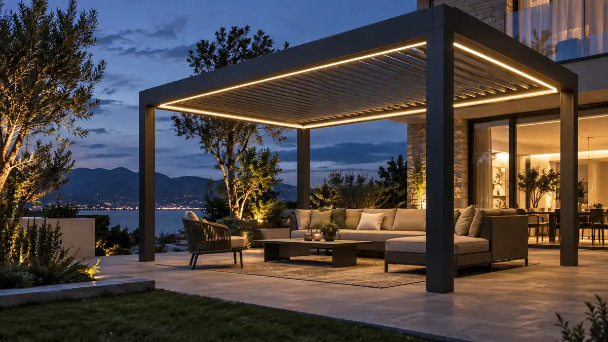
Why pergola LED strips develop dim ends
Voltage drop is the loss of electrical potential as current travels through resistance. In a pergola lighting system, that resistance exists in two places: the feeder cable from the driver or controller to the strip, and the copper paths inside the strip itself. Every connector, solder joint, splitter, fuse, and terminal adds another small contribution.
When the voltage at the far end falls below the strip’s intended operating condition, the LEDs no longer produce the same output as the first section. The visible symptoms can include a brightness gradient, a warmer-looking tail on white light, colour imbalance on RGB or RGBW products, or flicker when the control system is near its load limit. As ULTRA LEDs explains, voltage drop can occur in both the cable and the LED strip, so replacing only the external cable may not solve the whole problem.
OEM principle: if the customer can see the brightness change, the product specification was incomplete before the pergola left the factory. “The installer should have injected power” is not a product strategy.
The design mistake: treating a pergola perimeter as one continuous run
A pergola perimeter is not the same as a short cabinet-lighting installation. The route can cross several beams, pass through corner profiles, enter a control box, and use weather-resistant connectors at points that are mechanically convenient rather than electrically ideal. A perimeter may also contain different visual zones that should be dimmed together but not necessarily powered through one uninterrupted copper path.
That is why a single long end-fed strip is a risky default. The first part of the strip carries the current for everything downstream. The copper trace closest to the input sees the heaviest electrical load, while the far end receives the lowest voltage. A well-designed system divides the load into sensible zones and brings power to each zone through a defined path.
For a manufacturer, this changes the question from “How many metres can this strip run?” to four better questions:
- What is the maximum continuous strip length for this exact power density and voltage?
- Where are the approved feed points for a standard pergola module?
- What cable cross-section and connector family are included in the kit?
- What far-end voltage and brightness result must pass production validation?
12V or 24V: the rail voltage is an OEM decision
For the same electrical power, a 24V strip draws roughly half the current of a 12V strip. Lower current reduces resistive loss in the feeder and in the strip’s conductive paths. It also gives the system more voltage headroom before a given loss becomes visually significant. This is why 24V is usually the more forgiving starting point for larger pergola lighting packages, although the correct choice still depends on the strip construction, power density, control method, and product geometry.
VLEDSTAR’s مجموعة إضاءة البرجولات includes 12V and 24V strip options, with COB and SMD formats, multiple power densities, and outdoor protection choices. The relevant point for OEMs is not that one voltage wins every application. It is that the strip voltage, driver output, controller channel, cut length, and wiring plan must be selected together.
| Design choice | What it helps with | What it does not solve by itself |
|---|---|---|
| Move from 12V to 24V | Reduces current for the same wattage and improves distribution margin. | Does not remove losses caused by undersized cable, bad connectors, or excessive strip length. |
| Use a thicker feeder | Reduces the cable portion of voltage drop. | Does not repair voltage loss along the strip’s own PCB traces. |
| Use centre or dual-end feeding | Shortens the electrical path through the strip and improves uniformity. | Requires correct polarity, fusing, routing, and a connector layout designed for it. |
| Split into zones | Makes current, control, and troubleshooting more predictable. | Needs enough controller channels or a correctly engineered distribution system. |
Calculate the system before choosing the maximum strip length
Voltage-drop calculations do not need to be complicated, but they must include the complete current path. A useful first check for the feeder is:
The factor of two represents the outgoing and return conductors. For a more complete design, add the expected resistance of connectors, splitters, terminals, and the strip’s internal copper path. Then compare the result with the operating voltage and the manufacturer’s approved tolerance.
Do not turn a general rule into a universal warranty promise. Some lighting guides use a 5% design target, while individual strip manufacturers may specify a tighter limit. LEDWORLD’s technical guide uses 5% as a practical rule of thumb and illustrates why the same absolute loss is more severe at 12V than at 24V. For an OEM product, the final limit should come from the actual strip, driver, controller, and visual requirement being sold.
Use the highest credible load when sizing. RGBW strips may draw differently depending on the colour scene, and a mono strip can be tested at a lower brightness than the customer will use. The design should account for full-white operation, maximum permitted continuous length, supply tolerance, ambient temperature, and the resistance of the installed connection system.
Power injection is not a patch; it is a topology
Power injection works because it reduces the distance that current must travel through the strip’s internal copper. Depending on the geometry, that may mean centre feeding, feeding both ends, or dividing a long perimeter into parallel zones. ENTTEC’s guidance makes the practical symptom clear: a far end that dims, changes colour, or turns pink is often telling you that the supply path needs attention.
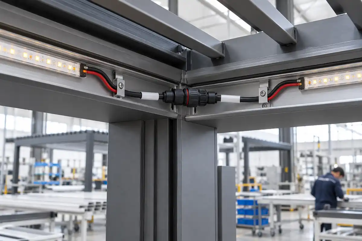
For pergola OEMs, the important engineering detail is that injection points must be designed, not improvised on site. Define:
- the location of each feed point in the aluminium structure;
- the polarity and connector keying;
- the cable gauge and maximum branch length;
- the protective device or channel limit for each branch;
- the service access required if a connector or strip section needs replacement.
Adding a thin jumper to a distant injection point only moves the bottleneck. The branch cable must be able to deliver the required current with acceptable loss. A waterproof connector can protect against moisture while still creating an electrical restriction if its contacts, crimp, or mating pressure are not suitable for the load.
Driver and controller sizing: leave room for real installations
A driver that is technically equal to the calculated strip load is not automatically a robust OEM choice. The driver must match the nominal voltage, deliver stable output under the expected load, and work correctly with the dimming method used by the controller. The controller channel must also be rated for the actual current, not just the nominal wattage printed on a marketing sheet.
VLEDSTAR’s نظام التحكم في البرجولا is built around integrated lighting and motor control, with a 24V mono-lighting channel specification shown at up to 300W on the product page. That kind of system-level architecture is valuable because the lighting output, channel capacity, RF control, motor functions, and sensors can be considered together. It does not replace load calculation; it gives the OEM a clearer platform on which to standardise the calculation.
Separate the following limits in your documentation:
- driver maximum output;
- controller channel maximum;
- recommended continuous load;
- maximum branch current;
- maximum cable length at the selected cross-section;
- maximum strip length before another feed or zone is required.
When those numbers are merged into one vague “supports up to X metres” statement, dealers cannot tell whether the limit is thermal, electrical, optical, mechanical, or simply a conservative recommendation. Good OEM documentation makes the boundary visible.
Validation that protects the brand after installation
The most useful production test is not just “does it light?” It is “does the complete supplied system remain uniform at its worst credible operating condition?” Build a representative pergola section or a repeatable bench fixture with the real strip, controller, driver, cable, connectors, splitter, and profile used in the kit.
At minimum, record:
- voltage at the driver output;
- voltage at the first strip segment;
- voltage at the farthest strip segment;
- input current at full rated load;
- brightness and colour consistency across the run;
- connector and driver temperature after a sustained test;
- behaviour during dimming, scene changes, and power cycling.
Measure the first strip segment separately from the driver output. That distinction tells you whether the loss is primarily in the feeder or inside the strip. A practical LED strip voltage-drop calculator and wiring guide also notes that field results can be affected by terminal quality, copper trace resistance, and conductor material. In other words, a calculation is a design gate, not a substitute for testing the supplied assembly.
How to turn voltage-drop control into a warranty policy
A warranty claim becomes difficult when the installation boundary is undefined. The strip may be blamed for a cable problem; the cable supplier may be blamed for a controller setting; the installer may be blamed for using a connector supplied in the kit. OEMs can prevent this circular argument by issuing a clear installation envelope with every lighting package.
That envelope should include the approved strip type, voltage, power density, maximum continuous section, feed topology, cable specification, connector orientation, controller channel limit, and commissioning test. If a dealer wants a longer perimeter, the documentation should show the approved zone or injection arrangement rather than leaving the decision to trial and error.
This is also where a manufacturing partner can add value beyond supplying a reel of tape. VLEDSTAR describes customized strip services for tailored lengths, PCB widths, and IP-rated solutions, as well as integrated lighting and control kits. For an OEM, the benefit is not only purchasing convenience. It is the opportunity to align the electrical design with the physical pergola, the brand’s installation method, and the dealer’s service process before mass production.
Our position: design the lighting kit as a serviceable system
Dim ends are rarely caused by one dramatic mistake. They are usually the accumulated result of a low-voltage choice, a long perimeter, a small cable, an extra connector, an optimistic load assumption, and a test that stopped when the first LED turned on. The OEM that treats each item separately may save a small amount on the bill of materials and spend much more on support.
The stronger approach is to make uniform brightness a product requirement. Choose the rail voltage with the route in mind. Split the structure into electrical zones. Specify feed points and cable sizes. Select a driver and controller with documented headroom. Test the far end, not just the input. Give dealers a wiring plan that can be followed without interpretation.
VLEDSTAR has worked in LED lighting and integrated pergola control since 2010, with product lines covering strip lights, spotlights, wall and post lights, lighting kits, and control systems. Our company profile explains the R&D and manufacturing focus behind those systems. For a new pergola platform, that experience is most useful when it is applied early, while the strip length, profile, cable route, controller, and service model are still open to engineering decisions.
Review your next pergola lighting architecture before production
Share the pergola module dimensions, strip voltage, power density, intended zones, cable route, and control requirements with VLEDSTAR. We can help you review the lighting and control architecture, define practical feed points, and develop an OEM-ready package designed for uniform output and easier dealer installation.
Contact VLEDSTAR about your pergola lighting project or review the pergola lighting solutions available for custom product development.

أرسل لنا طلبك