


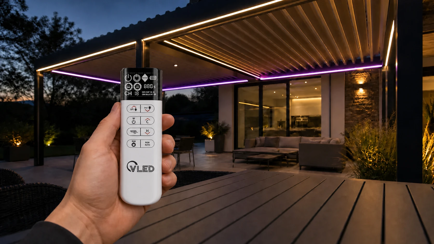
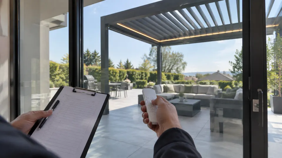
A motorized aluminum pergola can look flawless in the showroom and still fail the most ordinary real-world test: the homeowner stands behind a sliding glass door, presses the remote, and nothing happens. The dealer tries again from a different angle. The lights respond but the louvers do not. The roof works when the access cover is open, then becomes unreliable when the aluminum beam is closed. Everyone starts asking whether the remote battery is weak, whether the installer made a mistake, or whether the receiver is defective.
The uncomfortable truth is simpler: the RF system was not designed as part of the pergola. It was added to the pergola.
For manufacturers selling into the United States, Canada, the United Kingdom, and the European Union, this distinction matters. Aluminum louvered pergolas are not small indoor devices. They are large conductive structures with motors, LED drivers, long low-voltage cables, weather sensors, powder-coated profiles, sealed cavities, glass walls nearby, and sometimes several roof or lighting zones operating from one remote. RF reliability has to be engineered into that environment, not hoped for after production.
The manufacturer-first answer
Prevent RF signal problems by treating the receiver, antenna, controller enclosure, aluminum frame, lighting power system, and commissioning test as one RF-control assembly. The strongest approach is to define the RF path before the extrusion, control box, wiring harness, and service access are locked.
Why RF Fails Inside Aluminum Pergolas
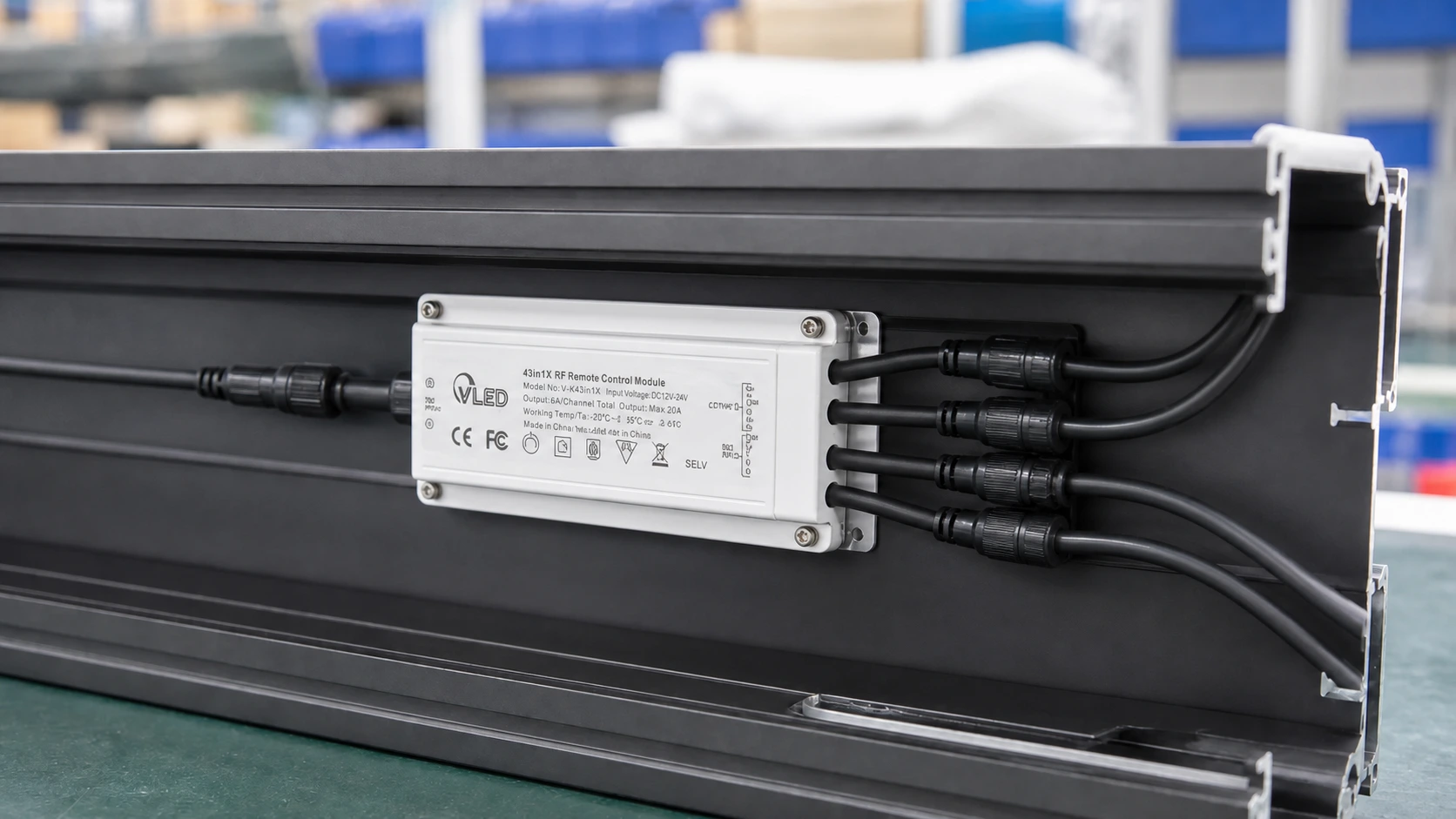
Radio frequency control works by moving energy between a transmitter and a receiver. That sounds simple until the receiver is placed inside or behind aluminum. Aluminum is conductive. It can reflect, attenuate, and reshape RF energy. It can also detune an antenna when the antenna sits too close to the metal surface. The result is not always a clean “works” or “does not work” condition. It is often intermittent behavior, which is worse for a dealer network because it feels impossible to reproduce.
In real projects, the RF path is affected by four overlapping conditions.
1. The frame becomes part of the RF environment
An aluminum pergola has posts, beams, louvers, brackets, gutters, motor housings, and access covers. If the receiver is buried inside a closed profile, the structure can behave like a partial shield around the receiver. If the antenna is pressed against the inside wall of the beam, the antenna no longer behaves like it did on the supplier’s open-air bench test.
This is why open-air range claims can mislead product teams. A remote-control system that performs well across a factory floor may lose margin once the receiver sits inside a powder-coated aluminum cavity, near a motor cable, with the user operating through glass or from the far side of the patio.
2. Antenna detuning reduces usable range
The antenna is not just a wire. It is a tuned RF component. At common pergola-control frequencies such as 433 MHz, a quarter-wave reference length is roughly 17 cm before practical antenna design factors are considered. That does not mean every receiver wire should be cut or changed to that length. It means the antenna geometry, clearance, orientation, and surrounding material all matter.
RF design training from Silicon Labs emphasizes core antenna concepts such as impedance, efficiency, radiation pattern, directivity, and gain. For pergola manufacturers, the practical lesson is direct: do not coil the receive antenna for neatness, trap it under a metal lid, clamp it to a conductive bracket, or hide it beside a switching power supply and then expect catalog range.
3. Reflections create dead spots
Aluminum does not only block RF. It can reflect it. In a backyard or hospitality terrace, the remote signal may bounce from louvers, glass doors, steel railings, stone walls, outdoor kitchens, heaters, and nearby vehicles. Sometimes reflected signals help. Sometimes they cancel or weaken the useful path at exactly the place where the user naturally stands.
This is one reason a pergola remote may work from one side of the structure and fail from another side at a similar distance. The issue may not be distance. It may be the installed RF pattern.
4. Electrical noise steals signal margin
A pergola controller is rarely alone. It may share an enclosure with LED drivers, motor relays, DC outputs, sensor inputs, app modules, and long cable runs. Switching power supplies, dimming circuits, motor starts, poor grounding, and unshielded routes can raise the noise floor around the receiver. When the received command is already weakened by aluminum, a small increase in noise can be enough to create missed commands.
That is why the control architecture matters. A professional sistema de controlo da pérgula should be evaluated as a complete electrical platform: RF remote, app, touchscreen, motor outputs, LED outputs, sensor logic, waterproof connectors, enclosure placement, and service access.
Prevent RF Problems Before the Pergola Profile Is Finalized
Homeowners judge smart control by convenience. Manufacturers are judged by repeatability. A system that works in one demo unit but causes confusion across dozens of dealers, climates, wiring layouts, and aluminum structures will quietly damage margin.
That difference changes the buying criteria. A homeowner may ask, “Can I use an app?” A manufacturer should ask, “Can our factory pre-wire it, can our dealer pair it quickly, can the user recover from mistakes, and can our service team explain it in two minutes?”
| Design decision | RF risk if ignored | Manufacturer action |
|---|---|---|
| Controller cavity | The receiver may be trapped inside a metal chamber with poor signal exposure. | Reserve an RF-aware receiver zone or use an antenna route that exits the metal cavity cleanly. |
| Access cover material | A metal service cover can change range after final assembly. | Test with the final cover installed, including gasket, screws, paint, and grounding condition. |
| LED driver location | Noise from dimming or switching circuits can reduce receiver sensitivity. | Separate RF receiver and antenna routing from high-current LED and motor wiring where possible. |
| Motor cable path | Motor starts and long parallel cable runs can inject noise into nearby receiver wiring. | Define harness routing, strain relief, grounding, and separation rules in the factory drawing. |
| Service access | Dealers may move or coil the antenna during installation or troubleshooting. | Make the approved antenna position obvious, protected, and repeatable. |
VLEDSTAR’s work in integrated lighting and controls is built around this kind of early architecture decision. Our smart pergola control system guide explains why manufacturers should specify the controller, sensors, lighting outputs, motor interface, and local control methods before the product line is treated as finished.
Treat Antenna Placement as Product Design
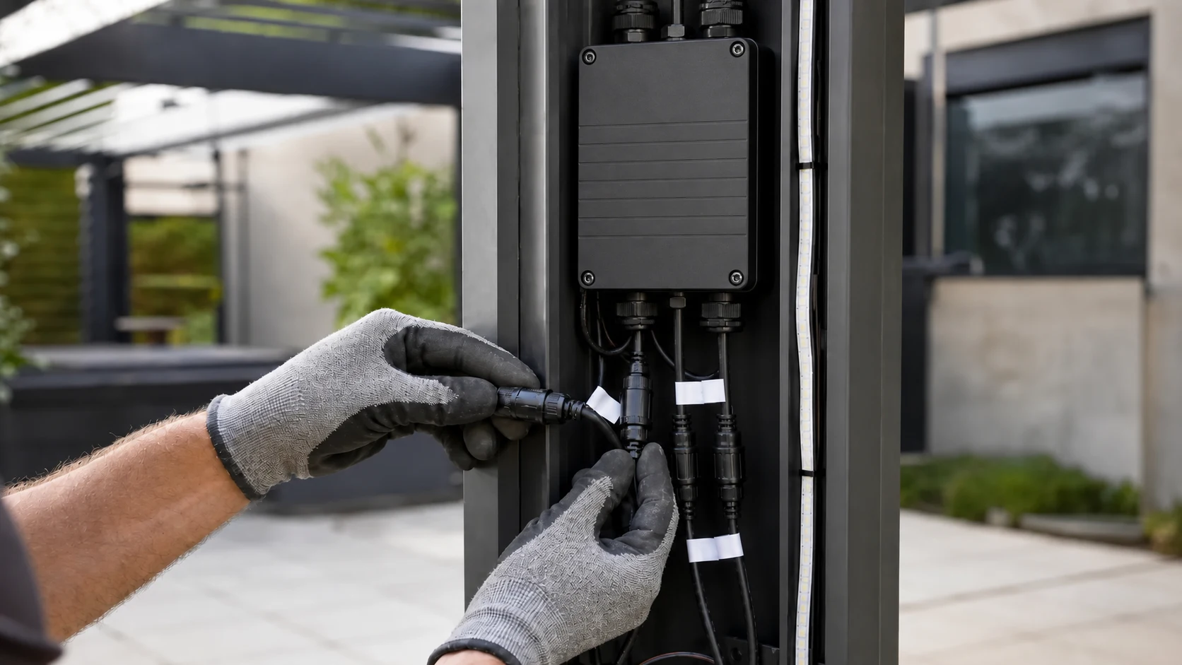
An antenna is often the cheapest-looking part of the control system, but it can decide whether the whole pergola feels premium. A beautiful remote is useless if the receiver cannot hear it. A compact control box is not an advantage if it hides the antenna in the worst possible place.
Good antenna planning starts with a few practical rules.
- Keep the receive antenna straight unless the antenna design specifically requires another geometry.
- Keep the antenna away from large metal surfaces, motor bodies, transformer cores, relay clusters, and high-current wires.
- Avoid coiling the antenna inside a control box, even if it looks tidy.
- Do not shorten, splice, fold, or replace the antenna without supplier approval and validation.
- Test the antenna with the final aluminum profile, powder coating, access cover, gasket, screws, and wiring harness.
- If the receiver must sit inside a metal cavity, evaluate an external antenna, RF-transparent window, or remote receiver location.
For pergola manufacturers, the goal is not to expose an ugly antenna. The goal is to create a controlled RF escape path that installers cannot accidentally destroy. A small plastic service insert, an approved antenna channel, or a short external antenna feed can be more professional than forcing the signal through a closed aluminum beam.
Antenna note for OEM teams
Do not make antenna modifications late in production without rechecking RF performance and regulatory implications. Changing antenna type, gain, cable length, or mounting position can affect range, emissions behavior, and compliance documentation.
Choose a Controller Architecture That Reduces RF Complexity
Many RF problems become worse because the pergola uses too many separate receivers. One receiver controls the louver motor. Another controls warm white LED strips. Another controls RGB lighting. A fourth is added for side screens or heaters. The homeowner sees a luxury product, but the control system behaves like a group of unrelated accessories.
Fragmented control increases the number of pairing procedures, antennas, power supplies, enclosure locations, and possible interference points. It also makes support harder. When a dealer receives a call that “the remote only works sometimes,” the real cause may sit anywhere across several receivers and power circuits.
A more robust OEM strategy is to consolidate control where it makes engineering sense. VLEDSTAR’s integrated pergola control unit is designed around one control platform for RF remote, Tuya app, touchscreen control, RGB lighting, mono lighting, linear actuators, tubular motors, and weather sensors. The related guide to using one pergola remote for actuators, mono LEDs, and RGB LEDs shows the same idea from the user-interface side. For RF reliability, this type of architecture can reduce random receiver placement and give the manufacturer one defined control center to validate.
That does not mean every function must be forced onto one board in every product. Large commercial installations may still need distributed modules. The principle is that the control map should be intentional. Every receiver should have a known location, known antenna condition, known power environment, known channel role, and known service procedure.
Do Not Let Lighting Integration Damage RF Margin
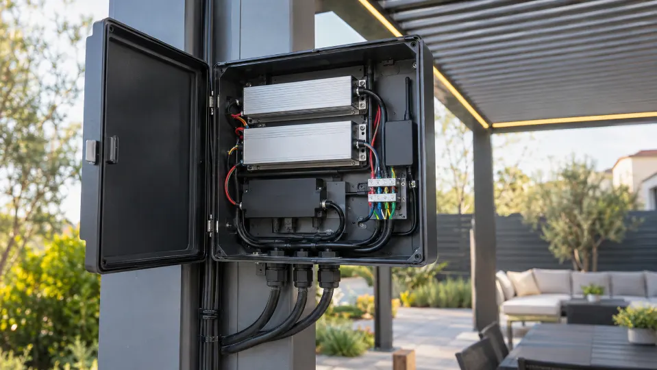
Integrated lighting is one of the strongest ways to differentiate a premium pergola line, especially in European and North American outdoor living projects. It also changes the RF problem. LED strip lights, downlights, RGBW circuits, drivers, splitters, connectors, and dimming outputs add current, wiring, and electromagnetic activity inside the same aluminum structure where the RF receiver must operate.
This is not an argument against integrated lighting. It is an argument for designing lighting and RF together.
On the VLEDSTAR pergola lighting solutions page, the product range includes recessed downlights, LED strip lights, wall lights, post lights, waterproof options, and integrated control kits. These components can create a strong product story for pergola manufacturers, but the wiring architecture should protect the receiver from unnecessary noise and confusion.
When lighting is part of the same pergola platform, specify these details early:
- Which LED drivers are used, and where they sit relative to the receiver.
- Whether mono, CCT, RGB, RGBW, or mixed lighting zones share the same control box.
- How long low-voltage LED runs are routed through beams and posts.
- Whether dimming is PWM-based and whether it affects receiver performance during low-brightness scenes.
- Which connectors, splitters, and cable glands maintain the intended outdoor protection level.
- How the installer can identify lighting channels without moving RF components.
VLEDSTAR’s article on why pergola lighting controls fail outdoors takes the same position from the reliability side: the pergola should not become a collection of afterthought accessories. Motion, light, sensors, waterproof connectors, power supply behavior, and controls need one repeatable system logic.
Build a Repeatable RF Test, Not a Hope-Based Range Claim
Open-air range is useful as a starting benchmark, but it is not enough for aluminum pergolas. A manufacturer should know how the remote performs in the final structure, with the final controller, final antenna routing, final lighting load, final motor wiring, and final access covers.
A practical RF validation plan should include both factory tests and pergola-like assembly tests. The goal is not to create a laboratory report for every order. The goal is to discover the weak design choices before dealers discover them in front of customers.
| Test condition | What it reveals | OEM pass expectation |
|---|---|---|
| Open-air baseline | Confirms transmitter, receiver, firmware, and pairing behavior before structure effects are added. | Stable command response at the supplier’s claimed baseline distance under controlled conditions. |
| Receiver inside final aluminum cavity | Shows whether the profile, cover, screws, and coating reduce RF margin. | No missed commands at realistic homeowner and dealer operating positions. |
| Remote used through glass doors | Checks a common residential use case in North America and Europe. | Reliable response from likely indoor control points, not only from directly under the pergola. |
| Motor moving while lights are dimming | Exposes noise or power instability during the highest-stress operating scenes. | Remote commands remain stable during motor start, stop, and LED dimming changes. |
| Multiple zones paired | Checks whether channel grouping creates user confusion or cross-control risk. | Individual and group commands remain predictable across roof and lighting zones. |
| After water exposure and temperature cycling | Reveals connector, corrosion, condensation, and enclosure issues that affect RF and power. | RF range, pairing memory, and receiver behavior remain stable after environmental stress. |
The test should be written into the product development process, not left as an informal final check. Record the receiver position, antenna orientation, cable path, enclosure state, firmware version, remote model, battery condition, and test distance. If a field issue appears later, this record gives the engineering team a baseline instead of a guess. For outdoor enclosure planning, the VLEDSTAR article on IP65, IP66, and IP67 pergola controllers and sensors is a useful companion because water protection, cable glands, and enclosure layout often affect the same control box decisions.
Make the Dealer’s Troubleshooting Path Short and Mechanical
Even a well-designed RF system needs a support process. Dealers should not have to improvise diagnostics on a ladder. Give them a short fault path that separates power, pairing, antenna, noise, and mechanical issues.
A professional dealer-facing sequence can be simple:
- Confirm the remote battery under load, not only whether the indicator light flashes.
- Confirm the controller has correct input voltage and stable output voltage.
- Test local wired control or panel control if available.
- Check whether only one function fails or all functions fail.
- Confirm the remote is on the correct channel or group.
- Check whether the antenna is straight, clear, dry, undamaged, and in the approved position.
- Test with the access cover open and closed to identify shielding effects.
- Run commands with lighting off, lighting dimmed, and motor moving to check noise-sensitive behavior.
- Review recent rain, wind, snow, or safety override status before assuming RF failure.
- Re-pair only after power, antenna, and channel state have been confirmed.
This is where integrated sensor logic also matters. A roof that ignores the remote during a wind or rain override may be working correctly, but the user may describe it as a failed remote. VLEDSTAR’s guides to pergola wind sensor thresholds e rain sensor placement for motorized louvered roofs explain why sensor priority should be treated as control logic, not just accessory selection.
RF Reliability Also Has a Compliance Dimension
RF performance is not only a customer-experience issue. Wireless products sold into regulated markets require attention to radio rules, documentation, labeling, and changes after approval. A pergola manufacturer should not treat the remote-control system as a generic accessory if the final product is sold under its own brand.
For the United States, radio frequency devices are covered under 47 CFR Part 15. For the European market, the Radio Equipment Directive sets a framework for radio equipment, including safety, electromagnetic compatibility, and efficient use of radio spectrum. The European Commission also outlines manufacturer responsibilities for CE marking, technical documentation, and conformity assessment.
The practical OEM message is this: do not casually change antennas, transmit power, receiver modules, enclosure materials, cable lengths, or firmware parameters after compliance planning. A small RF design change may be electrically helpful but documentation-sensitive. If a product line uses different regional remotes or frequencies, keep the versions clear in the BOM, manual, label, packaging, and dealer training material.
Smart-home planning adds another layer. Matter and other connected-home ecosystems are pushing the market toward more interoperable local control. The Connectivity Standards Alliance describes Matéria as a standard intended to improve secure and reliable connectivity across brands. For pergola OEMs, this does not remove the need for stable RF local control. It reinforces the same principle: the user interface may evolve, but the physical outdoor control layer still has to work when the phone, router, cloud account, or voice assistant is not available.
RF Reliability Checklist for Aluminum Pergola OEMs
Use this checklist before freezing a new motorized pergola control package.
- The receiver location is defined in the mechanical drawing, not left to the installer.
- The antenna position is shown in the assembly manual with clear do-not-move guidance.
- The antenna is not coiled, squeezed, grounded, cut, or hidden behind a final metal cover without testing.
- The control box has enough separation between RF components, motor outputs, LED drivers, relays, and high-current cable runs.
- The pergola has been tested with all access covers, gaskets, fasteners, and powder-coated parts installed.
- The remote works from realistic user positions, including through patio glazing and from common seating areas.
- Lighting dimming and motor movement do not create missed RF commands.
- The dealer can identify channel assignment without opening sealed electronics unnecessarily.
- The system has a wired or local fallback control route where the project value justifies it.
- The RF module, antenna, frequency, firmware, label, and regional compliance documents match the final shipped configuration.
Where VLEDSTAR Fits in the RF Reliability Conversation
VLEDSTAR is not a pergola frame manufacturer. That is exactly why our role is useful to pergola OEMs. We focus on the lighting and control layer that often decides whether a premium aluminum structure feels intelligent in daily use.
According to the VLEDSTAR factory profile, the company started in LED lighting in 2010 and has built experience in R&D, manufacturing, and sales of pergola lighting and integrated control systems. The product range includes LED spotlights, strip lights, deck lights, post and wall lights, complete lighting kits, and control systems for motorized structures such as louvered and retractable roofs.
That background matters because RF issues often sit between categories. The structure team thinks about aluminum. The lighting team thinks about LED drivers and voltage drop. The motor supplier thinks about torque and limits. The app supplier thinks about onboarding. The dealer thinks about how to make everything work on site. A pergola manufacturer needs a control partner who can connect those concerns into one package.
For manufacturers developing a new product line, VLEDSTAR can support the RF-control conversation in practical ways:
- Reviewing controller placement against aluminum profile constraints.
- Planning RF remote, app, touchscreen, and wired control hierarchy.
- Coordinating mono, CCT, RGB, and RGBW lighting control with motor outputs.
- Helping define antenna routing and dealer-friendly assembly instructions.
- Supporting weather sensor logic so rain, wind, sun, and snow inputs do not create false “remote failure” complaints.
- Adapting control packages for OEM branding, channel logic, wiring harnesses, and product-tier strategy.
If your current product line still uses separate remotes for louvers, lights, screens, and accessories, the RF problem is probably bigger than range. It is a system architecture issue. Start with the control platform, then fit the remote, antenna, lighting, sensors, and enclosure around it.
The Strong Position: RF Is a Product Design Responsibility
Pergola manufacturers should stop treating RF performance as a small electronics detail. In aluminum pergola structures, RF reliability belongs in the same design conversation as extrusion geometry, drainage, motor selection, lighting layout, weather sealing, and dealer installation time.
A remote-control complaint may sound minor, but it touches the whole business. It affects dealer confidence, warranty cost, online reviews, showroom trust, and the buyer’s feeling that the pergola is truly premium. The strongest manufacturers will not win by adding more buttons or louder smart-home claims. They will win by making the system behave correctly in the real metal structure, in the real patio environment, with the real installer and user.
Plan RF Reliability Before Your Next Pergola Launch
If you are developing an aluminum louvered pergola, upgrading a control kit, or trying to combine motors, LED lighting, sensors, RF remote, app control, and dealer-friendly wiring into one OEM package, VLEDSTAR can help review the architecture before field problems become warranty costs.
Contact VLEDSTAR or explore our sistema integrado de controlo de pérgulas to start building a more reliable control platform for your next pergola model.

Pingback: Pergola Lighting Controls for Outdoor Kitchens and Dining Areas
Pingback: Smart Pergola Upgrade Packages: Basic Remote, App Control, Sensors, and Premium Lighting