


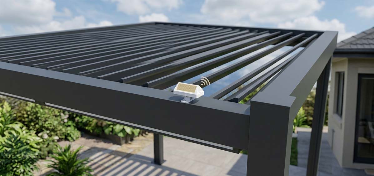
Search results around pergola rain sensors usually answer a simple homeowner question: will the roof close when it rains? That answer is useful, but it is too shallow for manufacturers. For a factory, the better question is different: where should the sensing point be designed, mounted, wired, tested, documented, and serviced so the automation remains reliable across different installers, roof sizes, climates, and control architectures?
Search results around pergola rain sensors usually answer a simple homeowner question: will the roof close when it rains? That answer is useful, but it is too shallow for manufacturers. For a factory, the better question is different: where should the sensing point be designed, mounted, wired, tested, documented, and serviced so the automation remains reliable across different installers, roof sizes, climates, and control architectures?That is the position of this article. Rain sensor placement should be treated as part of the louvered roof control design, not as a final accessory attached wherever the installer finds a convenient screw location. A sensor mounted in a sheltered corner can delay closure. A sensor mounted beside a drainage splash path can cause nuisance triggers. A wireless sensor placed behind aluminum beams can create intermittent signal loss. A wired sensor without a drip loop can become the water path into the controller. None of these problems look dramatic on a product brochure, but they show up quickly in warranty calls.
At VLEDSTAR, our work sits at the junction of low-voltage pergola lighting, RF controls, actuators, sensors, and OEM-ready control platforms. That makes rain sensor placement a practical manufacturing topic for us. The sensor itself matters, but the system around it matters more.
What the current market usually misses
Competitor pages and product listings often describe the same benefit in different words: the sensor detects rain and automatically closes the louvers. Some pages show a solar rain sensor as an optional accessory. Some explain that capacitive or optical rain detection can send a command to the control unit. Some installer-focused content discusses sensitivity settings, and major motor brands such as Somfy show that sensors may support wall, pole, or gutter mounting depending on the product.
Those points are valid. They also leave an important gap. For manufacturers, the risk is not whether rain detection exists. The risk is whether the roof design, control box, cabling path, bracket, RF environment, installer instructions, and commissioning process make rain detection repeatable.
This is where the article’s viewpoint is deliberately engineering-led: rain sensor placement should be specified at the factory level first and adapted by the installer second. If the factory provides no preferred sensing zone, the installer becomes the control system designer on every jobsite. That produces uneven results, even when everyone involved is competent.
Manufacturer’s opinion: a rain sensor should be positioned to detect the first representative rainfall hitting the roof area, not the first splash, drip, or trapped water event near the roof. It should trigger early enough to protect the system, but not so nervously that owners disable it after a week.
The core placement principle: exposed, representative, serviceable
The best rain sensor location on a motorized louvered roof is exposed to natural rainfall, representative of the roof’s weather exposure, and serviceable without dismantling the structure. If one of those three conditions is missing, the system will probably behave inconsistently.
Exposed
The sensor needs direct access to rain. It should not sit under a building eave, under a tree canopy, on the underside of a beam, inside a gutter channel, or behind a vertical fascia that shields it from the first drops. This sounds obvious, yet sheltered placement is common because sheltered areas are easier to reach and easier to wire.
Weather measurement standards are not written for pergola control systems, but they are still useful as a reminder: precipitation devices require careful exposure and should avoid nearby obstructions that distort rainfall. The U.S. National Weather Service gives rain gauge siting guidance that emphasizes open exposure away from trees and buildings, and the World Meteorological Organization Guide to Instruments and Methods of Observation is the reference framework behind professional weather instrumentation. A pergola rain sensor is not trying to measure rainfall accurately, but it still needs rainfall to reach it without being blocked.
Representative
Representative does not mean mathematically perfect. It means the sensor sits where rainfall behavior matches the part of the roof the control system is trying to protect. On a single-bay residential roof, that may be an exposed top beam near the weather side. On a large hospitality terrace, the answer may be multiple zones because one end of the roof can be sheltered by a wall while the other end is exposed to wind-driven rain.
The sensor should not be placed where water arrives only after the roof has already started draining. If the sensing face is triggered by gutter overflow or by water dripping from an upper balcony, the control system is no longer responding to rain. It is responding to local water behavior.
Serviceable
Rain sensors live outdoors. They see UV, dust, pollen, salt air, insects, cleaning water, snow in some markets, and occasional physical contact during roof maintenance. A perfect sensing location that cannot be inspected, cleaned, replaced, or re-paired is not a good production location. Service access should be part of the bracket and cable plan.
This is why the rain sensor belongs in the same conversation as the full control architecture. A product team designing an OEM pergola control platform should decide where sensor inputs, RF reception, actuator outputs, lighting loads, wall switches, and app control meet. Placement is not a separate installer note. It is part of the product’s service logic.
Factory guidelines for louvered roof manufacturers
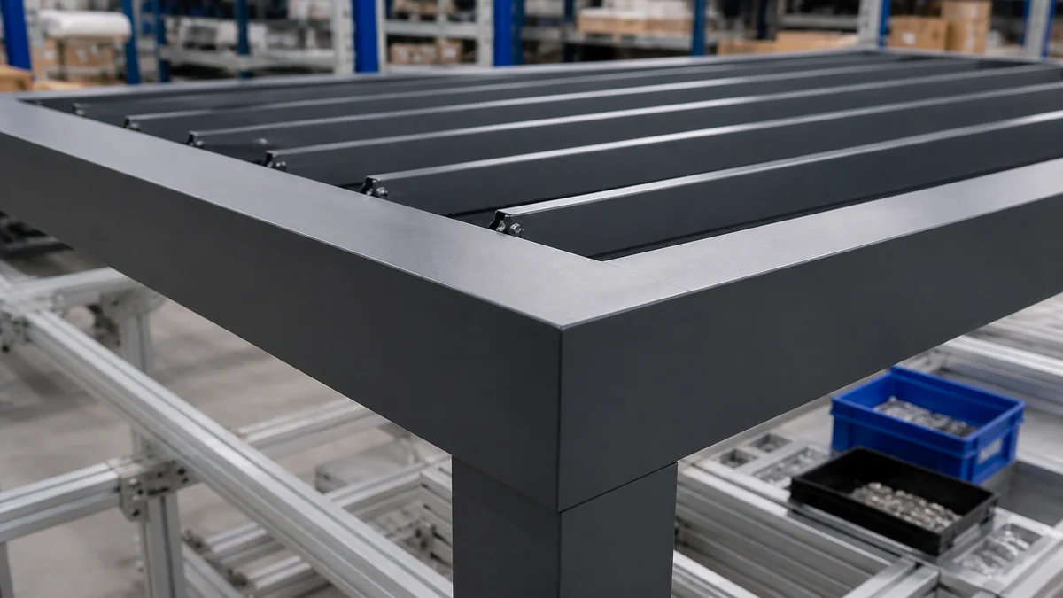
Factories can reduce installation variation by designing rain sensor placement into the roof system before production. The goal is not to remove installer judgment. The goal is to give installers a controlled starting point.
Define a preferred sensing zone, not a vague instruction
“Mount the rain sensor outdoors” is not enough. The factory manual should identify one or more preferred sensing zones by roof type. For example, the preferred zone may be on an exposed top beam near the leading weather edge, clear of louver rotation, clear of gutter splash, and within a defined cable route back to the controller.
For modular roofs, the preferred zone can be marked in the extrusion, bracket kit, or installation drawing. For custom roofs, the manual should show a hierarchy: primary zone, acceptable alternate zone, and prohibited zones. This makes the installer’s decision visible and reviewable.
Coordinate the sensor with louver movement
The sensor must remain exposed in the roof states that matter. A louvered roof is not a fixed surface. Louvers rotate, water direction changes, shadows move, and air pressure changes under the roof. The sensor should not be covered by the louver blade when the roof is open, hidden by the blade when the roof is partially tilted, or hit by mechanical movement during closing.
Factories should test the sensor location through the full motion range. This is especially important when one control system operates louvers, integrated LEDs, side screens, fans, or heaters. The more functions that share a controller, the more important it becomes to define weather priority logic clearly. VLEDSTAR discusses this broader control issue in its guide to integrating rain, wind, and sun sensors with pergola louvers and lighting.
Separate sensing logic from decorative lighting logic
Integrated lighting adds value to a louvered roof, but it also adds wiring, drivers, aluminum channels, RF considerations, and thermal conditions. The rain sensor signal should not be treated as an afterthought on the same physical path as high-load lighting cables unless the controller and wiring design are built for it.
For OEMs, the question is not only “does the sensor close the roof?” It is also “does the sensor remain stable when the LED driver switches, when RGBW channels dim, when the motor starts, and when the RF receiver is inside an aluminum structure?” These are the types of issues covered in VLEDSTAR’s outdoor pergola lighting control failure analysis ve RF pergola controller troubleshooting guide.
Specify the enclosure and connector strategy
A rain sensor placement plan is incomplete without an enclosure plan. The visible sensor may be rated for outdoor use, but the connector, cable exit, junction point, and control box entry are where many water problems begin. The IEC 60529 standard listing for enclosure protection codes is useful here because it reminds teams that IP ratings describe tested resistance to dust and liquids at the enclosure level. They do not automatically guarantee that a full installed cable path is protected.
Factory documentation should define the cable gland, connector orientation, drip loop, strain relief, bend radius, and service loop. For wireless sensors, the equivalent factory decision is the antenna path, pairing procedure, signal confirmation method, and battery or solar exposure requirement.
Build the rain sensor into the BOM
Rain sensor placement becomes easier when the sensor is part of the standard control BOM rather than a late accessory. A BOM can define the sensor technology, bracket, cable length, connector type, control input, firmware behavior, and test process. VLEDSTAR’s Pergola kontrol sistemi malzeme listesi kontrol listesi is a useful internal link for OEM teams that want to standardize these choices before production.
| Factory decision | Why it affects placement | Recommended output |
|---|---|---|
| Sensor technology | Capacitive, optical, wired, wireless, heated, or solar-powered sensors behave differently in mist, condensation, snow, shade, and drying cycles. | Define the use case, climate limits, sensitivity range, and test method. |
| Mounting bracket | A weak bracket encourages installers to improvise and may change sensor angle after transport or service. | Provide a roof-specific bracket with fixed orientation guidance and corrosion-resistant fasteners. |
| Cable path | Poor routing can pull water into the controller or place signal wiring beside noisy motor and lighting loads. | Provide a sealed route with drip loop, strain relief, and separation from high-current wiring where practical. |
| Controller logic | Placement cannot compensate for poor weather priority, false-trigger handling, or manual override behavior. | Document rain priority, dry reset, delay, override limits, and diagnostic feedback. |
| Installer documentation | The same hardware can perform very differently if the manual leaves placement open to interpretation. | Show preferred, alternate, and prohibited zones in the installation guide. |
Installer guidelines for site work
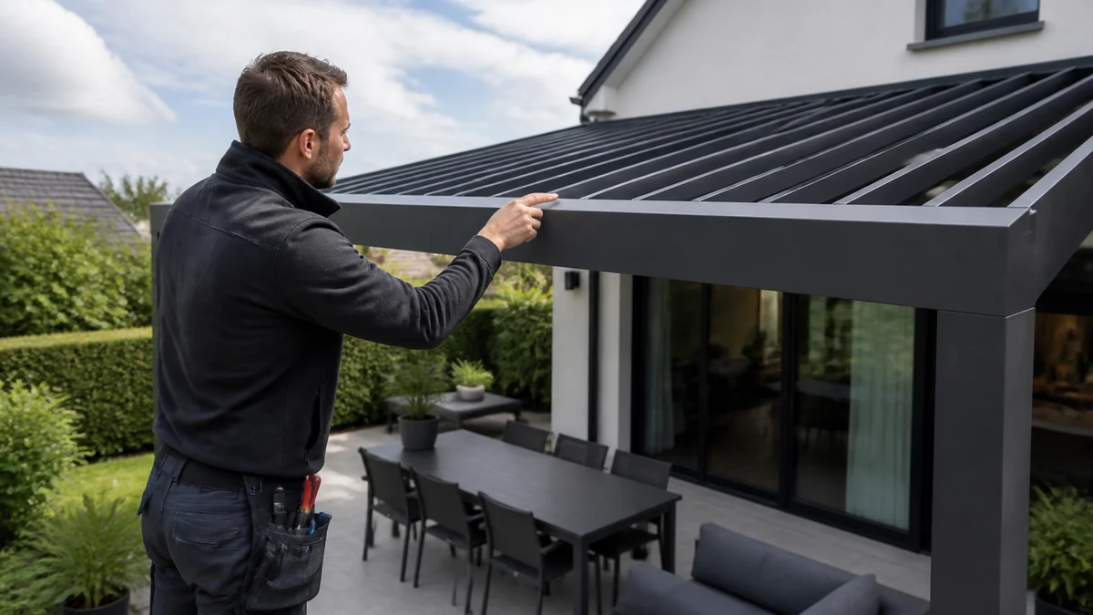
Installers should not simply look for the nearest flat surface. The roof environment should be read before drilling. A five-minute placement review can prevent years of nuisance service calls.
Start with the weather side of the structure
Identify where rain usually reaches the roof first. In many projects, this is the open side facing prevailing storms. In other projects, it is the corner most exposed to wind-driven rain because nearby walls redirect airflow. On commercial terraces, building geometry can create very different exposure across the same roof.
If the roof is attached to a building, do not assume the house side is the best side simply because wiring is easier. A sensor tucked against the wall may detect rain later than the furniture, integrated lighting channels, or outer louver field.
Check obstruction and splash behavior
Look above and around the proposed location. Trees, roof overhangs, balcony edges, gutters, signage, screens, and upper structures can block or delay rainfall. Then look for splash sources: downspouts, roof valleys, irrigation spray, drainage outlets, and surfaces where water can rebound onto the sensor.
The goal is to detect falling rain, not random water contact. A sensor that closes the roof whenever a nearby gutter splashes will teach owners to disable automation.
Keep the sensor clear of louver sweep and service movement
Operate the louvers through open, tilt, and closed positions before finalizing the location. Confirm that the sensor face is not shaded or covered in the operating state that matters for rain detection. Confirm that maintenance access, cleaning tools, and future replacement are realistic.
Protect the electrical path
For wired sensors, route the cable so water cannot run along it into the controller. Use a drip loop before the enclosure entry. Avoid cable tension. Keep connectors accessible but protected. Where the roof includes LED strips, downlights, actuators, and RF receivers, avoid placing low-level sensor wiring directly beside high-current switching paths unless the control system has been designed for that routing.
For wireless sensors, test communication with the louvers open and closed. Aluminum beams can change signal behavior. A signal that works on a workbench may be unreliable after the sensor is mounted near metal, lighting channels, and motor housings. If the pergola uses Somfy, Nice, Teleco, Tuya, RF, or custom control paths, confirm the intended pairing and receiver logic. VLEDSTAR’s guide to lighting kit compatibility with Somfy, Nice, and Teleco motors explains why compatibility should be addressed at system level rather than accessory level.
Commission the sensor with the roof, not on its own
A rain sensor test is not complete when an LED indicator flashes. The installer should verify that the sensor triggers the correct control response: louvers close in the intended direction, multi-motor roofs stay synchronized, manual commands behave as specified, lighting remains safe, and the system resets according to the manufacturer’s dry-time logic.
This is especially important for roofs that combine louvers with integrated lighting and actuator kits, such as VLEDSTAR’s pergola linear actuator and LED strip lights kit. Once lighting and movement share the same outdoor structure, the rain response is part of the total product experience.
Locations that create late closing or false triggers
Most rain sensor complaints come from predictable placement errors. These locations should be treated as prohibited or high-risk unless the factory has specifically designed and tested for them.
| Konum | Common failure mode | Better approach |
|---|---|---|
| Under a building eave or balcony | Rain reaches the roof before it reaches the sensor, causing late closure. | Move the sensor to an exposed top beam or approved weather-side bracket. |
| Inside or beside a gutter channel | Sensor reacts to drainage, splash, or standing water rather than rainfall. | Mount before the drainage path, not inside it. |
| On a sheltered wall-facing post | Wall protection delays detection and may create uneven behavior in wind-driven rain. | Use the exposed roof perimeter or factory-approved alternate zone. |
| Near irrigation spray or downspout discharge | False closure during watering, cleaning, or overflow events. | Separate the sensor from artificial water sources and splash zones. |
| Behind large aluminum beams or inside a metal cavity | Wireless sensor commands become intermittent or range becomes unstable. | Confirm RF path during commissioning or choose a wired input. |
| Where maintenance requires disassembly | Dirty or failed sensors remain in service because replacement is too difficult. | Place the sensor where inspection and cleaning are realistic. |
One sensor is not always enough
For a small freestanding pergola, one well-placed rain sensor is often adequate. For larger roofs, multi-bay structures, restaurant terraces, hotel courtyards, or roofs interrupted by walls and screens, one sensor may not represent the whole roof. The larger the structure, the more likely it is that one zone will experience rain before another.
Manufacturers should decide when to support multi-zone sensing. The decision can be based on roof size, number of independent motor groups, exposure variation, and project type. A hospitality roof above dining tables usually has a lower tolerance for late response than a residential shade structure above a casual seating area.
Multi-zone sensing also raises control questions. If Zone A detects rain and Zone B remains dry, should the whole roof close? Should only one motor group close? Should screens retract or lower? Should lighting stay on? These decisions belong in the controller’s priority matrix, not in the installer’s improvisation. VLEDSTAR’s article on pergola rain sensor automation goes deeper into how sensor signals, motor communication, and weather priority logic work together.
False triggers are a product-design problem, not only a sensor problem
A roof that closes too late creates visible failure. A roof that closes too often creates a quieter failure: the owner disables automation. For OEMs, both outcomes damage the product.
False triggers can come from condensation, fog, roof washing, irrigation, gutter splash, insects, snow melt, or residue on the sensing surface. Some sensor types include adjustable sensitivity, heating, optical detection, dry-time logic, or demo modes for commissioning. For example, Somfy’s professional sensor pages describe outdoor rain and sun sensors with selected thresholds, flexible mounting options, and pergola applications. Teleco’s sensor category includes a wired rain sensor with integrated heating intended to reduce unwanted activation in ice or snow conditions.
The manufacturer’s job is to choose a sensible default. For louvered roofs, we generally favor a conservative rain response over a delayed response, especially for commercial and hospitality projects. But conservative does not mean careless. The sensor should close the roof when weather protection is needed, not when water from a hose briefly touches a badly chosen bracket location.
Commissioning and handover checklist
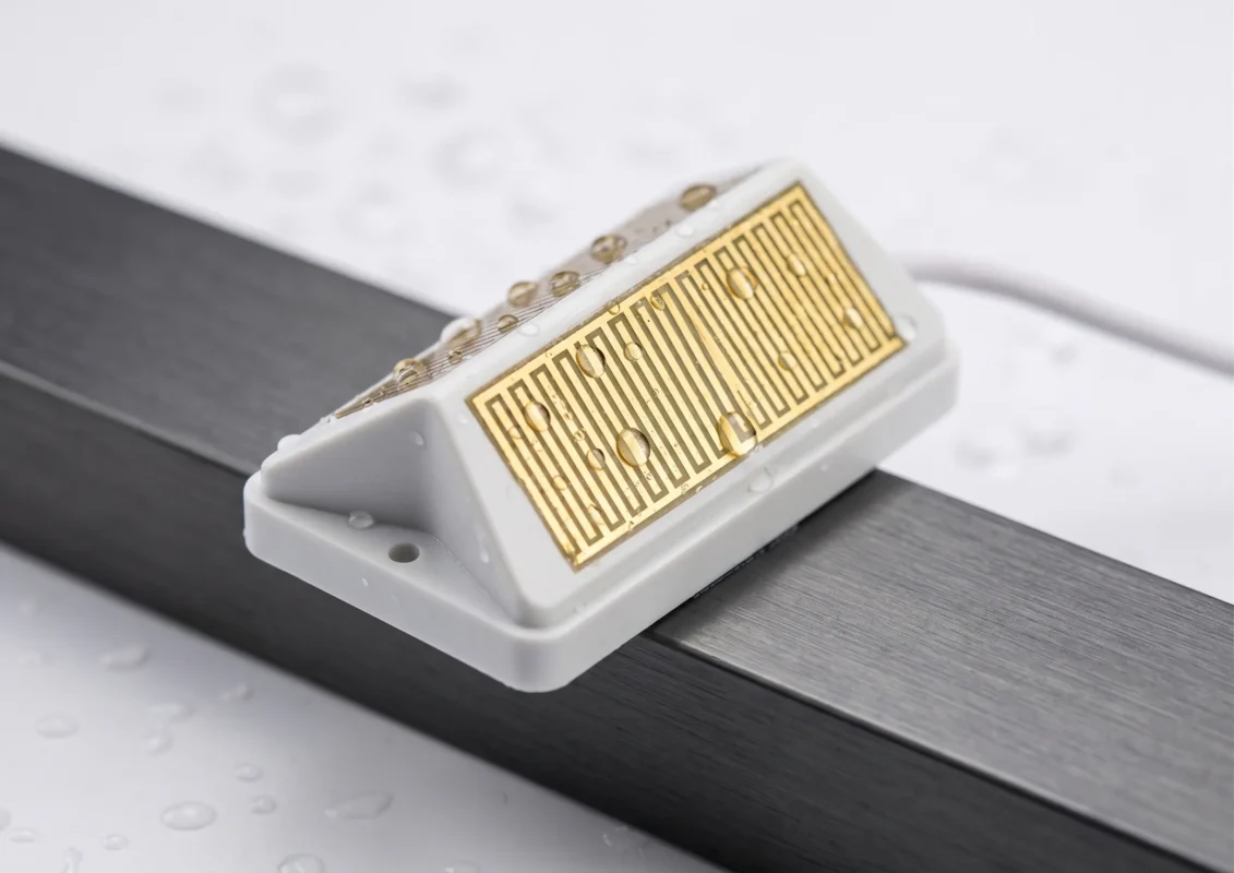
Commissioning should prove the complete weather response. A quick sensor wetting test is helpful, but it is only one step.
- Confirm the sensor is in the factory-approved placement zone or record the reason for an alternate location.
- Check that the sensor face is exposed to rainfall and not blocked by louvers, walls, trees, gutters, or accessories.
- Inspect cable routing, drip loop, connector orientation, strain relief, and enclosure entry.
- For wireless sensors, test signal reliability with the roof fully open, partially tilted, and closed.
- Trigger the sensor using the manufacturer’s recommended test method, not an uncontrolled flood of water.
- Verify that all relevant motors close correctly and that multi-motor groups remain synchronized.
- Confirm rain priority over manual open commands according to the product’s safety logic.
- Confirm dry reset, delay, or re-open behavior according to the system settings.
- Check that integrated lighting, RF remotes, wall switches, and app controls still behave correctly after the rain event.
- Explain the sensor location, cleaning expectation, override behavior, and service path to the dealer, installer, or owner.
For manufacturers building dealer networks, this checklist should be part of installer training. For installers, it should be part of the signed handover. For OEMs, it should be included in the quality system because the rain sensor is a weather protection function, not a decorative option.
How VLEDSTAR approaches rain sensor integration
VLEDSTAR develops and manufactures pergola lighting and control systems for outdoor structures, with experience in LED kits, RF remotes, actuators, sensors, low-voltage power distribution, and OEM control integration. Our perspective is system-based: a reliable pergola roof is not built by combining unrelated accessories. It is built by aligning mechanical movement, lighting load, sensor logic, RF behavior, waterproofing, and installer documentation.
That is why our content often focuses on manufacturer-level decisions, such as how to source a pergola lighting and control system, how to specify motorized louvered pergola control systems, and how to design commercial pergola controls for hospitality. Rain sensor placement belongs in that same category. It is small hardware with large consequences.
SSS
Should the rain sensor be mounted on the roof or on a nearby wall?
For most motorized louvered roofs, the sensor should be mounted on an exposed part of the pergola structure or an approved bracket where it can detect rain before water reaches the protected area. A nearby wall may be acceptable only if it is truly exposed and approved by the sensor and roof manufacturer. Sheltered wall placement often causes late closing.
Is a gutter-mounted rain sensor a good idea?
It depends on the sensor design and the roof system. Some sensor products provide gutter mounting hardware, but the installer still needs to avoid locations where drainage splash, overflow, or standing water will create false triggers. The key is to detect rainfall, not the gutter’s water behavior.
Can one rain sensor control a large louvered roof?
Sometimes, but not always. One sensor can work on a small roof with uniform exposure. Larger multi-bay roofs, commercial terraces, and roofs affected by walls or wind corridors may need multiple sensing zones or a more deliberate control strategy.
Should rain override manual control?
In most professionally designed louvered roof systems, rain should have priority over manual open commands while the sensor is active. The exact override behavior should be documented by the manufacturer, especially where wind, snow, screens, heaters, and lighting are also connected to the control platform.
How often should the sensor be serviced?
The installer or manufacturer should define the maintenance interval based on climate, dust, pollen, salt exposure, and sensor type. As a practical rule, the sensor should be visually inspected and cleaned whenever the roof receives routine service. It should also be checked after construction work, repainting, heavy storms, or unexplained automation behavior.
Design the rain response before the first roof ships
If your louvered roof line includes motors, LEDs, RF remotes, app control, rain sensors, wind sensors, or dealer-installed accessories, placement should be designed into the system before production. VLEDSTAR helps pergola manufacturers develop integrated lighting and control solutions that are easier to install, easier to support, and better suited to outdoor conditions.
Explore VLEDSTAR’s pergola control system solutions or contact the team through VLEDSTAR’s factory profile to discuss OEM-ready lighting, actuator, RF, and sensor control integration for your next louvered roof platform.

Pingback: Linear Actuator vs Tubular Motor for Louvered Pergolas: Control Implications
Pingback: Tek Bir Pergola Uzaktan Kumandasından İki Aktüatör, İki Mono LED Bölgesi ve Bir RGB Bölgesini Nasıl Kontrol Edebilirsiniz?
Pingback: Entegre Kontrol Sistemleri Bayilerin Pergola Kurulum İşçiliğini Nasıl Azaltıyor?
Pingback: Akıllı Pergola Kontrol Sistemi Nedir? Bir Üreticinin Açıklaması
Pingback: Pergolalar için Sahne Kontrolü: Akşam Yemeği Modu, Fırtına Modu, Gün Batımı Modu ve Bayi Ön Ayarları
Pingback: Pergola Scene Control for OEMs: Dinner & Storm Presets
Pingback: Pergola Kontrol Cihazları ve Sensörleri için IP65, IP66 veya IP67: Asıl Önemli Olan Nedir?
Pingback: Alüminyum Pergola Yapılarında RF Sinyal Sorunlarını Önleme Yöntemleri
Pingback: Smart Pergola Upgrade Packages: Basic Remote, App Control, Sensors, and Premium Lighting