


For pergola manufacturers, the most expensive wiring problems are rarely dramatic failures on the production line. They are the small decisions that become expensive after installation: a controller that does not fit inside the profile, a light circuit that exceeds the dimmer output, a motor cable routed through a drainage path, or a harness that cannot be replaced without dismantling the roof.
This is why a wiring diagram should be treated as a product-development document, not simply an installer’s sketch. It needs to communicate what is powered, what is controlled, where each cable travels, how connectors are identified, and how the system behaves when a sensor or control device is unavailable.
In this guide, we explain the wiring concepts we use when developing lighting and control systems for louvered and retractable pergolas. The examples are architecture concepts, not universal installation instructions. Final conductor sizing, protection, earthing, enclosure selection, and approval requirements must be confirmed by the responsible electrical professional under the applicable local code and the exact motor and power-supply documentation.
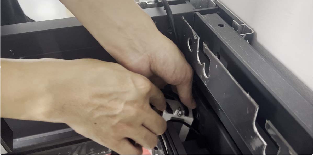
Start with the system architecture, not the cable colors
The first useful wiring diagram answers a simple question: which functions share a system, and which functions must remain electrically separate?
A typical motorized louvered pergola can contain five functional layers:
- Incoming supply and isolation.
- Power conversion for low-voltage lighting and controls.
- Motor or actuator outputs for louver movement.
- Lighting outputs for downlights, strip lights, or RGB/RGBW fixtures.
- Inputs and communication for remotes, apps, wall panels, and weather sensors.
These layers may sit in one integrated enclosure, but they should still be shown as separate blocks. A good diagram makes the boundaries visible even when the customer wants “one remote for everything.” Integration is a control decision; it does not mean every load uses the same voltage, cable, connector, or protection method.
AC SUPPLY / SITE ISOLATION
          |
          +---- [Approved power supply or motor supply] ---- MOTOR CONTROL ---- actuator / tubular motor
          |
          +---- [DC LED power supply] ---------------------- LIGHT CONTROL ---- spotlights / strips / wall lights
          |                                                        |
          |                                                        +---- RF remote
          |                                                        +---- app or wall panel
          |                                                        +---- wind / rain / sun input
          |
          +---- protective earth and bonding where required by the equipment and local code

Key concept: one user interface can coordinate several channels while each power path
is still documented, rated, protected, and tested on its own.
Two motor architectures require two different wiring concepts
“Pergola motor wiring” is not one standard. The diagram changes significantly depending on whether the roof uses a low-voltage linear actuator, a tubular motor, or a manufacturer-specific motor module.
Low-voltage linear actuator system
A linear actuator system normally includes a DC supply, one or more actuator outputs, travel or position feedback where supported, and a controller that manages direction, synchronization, current limits, or obstacle behavior. The control board may reverse polarity, use dedicated drive channels, or communicate with an actuator that contains its own electronics. Never infer the terminal function from the wire count alone.
For a multi-motor roof, the diagram should identify each output by physical roof zone, not only by channel number. “M1” is useful to the engineer; “North roof module actuator” is useful to production, service, and the installer. If two actuators must move together, show whether synchronization occurs mechanically, electronically, or through software.
VLEDSTAR’s نظام التحكم المتكامل في البرجولا describes a configuration that can manage multiple linear actuators, lighting channels, and weather inputs from a combined RF, app, and touchscreen control environment. For an OEM, the important design question is not simply the maximum channel count; it is whether the selected actuator, output stage, feedback method, and mechanical roof design have been validated as one system.
Tubular motor system
A tubular motor may be mains-powered, low-voltage, radio-controlled, or connected to a dedicated receiver. Some systems place the control intelligence in the motor head; others use a separate receiver or control unit. The diagram must therefore show the actual motor family and its approved interface instead of representing every motor as a generic two-wire load.
For example, Somfy documentation distinguishes between motor wiring, control-unit wiring, and weather-sensor connections. Its pergola control-unit material also warns about outdoor cable routing, cable protection through metal walls, water ingress, and cable-length limits. These are useful reminders for any pergola OEM: the wiring route and the connection enclosure are part of the product design, not details to leave until site installation. See the Somfy Pergola Tilt io control-unit documentation and the Somfy Pergola io installation overview for examples of manufacturer-specific motor and sensor logic.
Engineering rule: If a motor supplier changes, revise the wiring diagram, connector key, commissioning procedure, and compatibility statement. A new motor is not automatically a drop-in replacement because the power, direction, limit, feedback, and radio interfaces may all change.
Separate the lighting power path from the motor control path
Lighting and roof movement can share a user experience, but they should be separated in the electrical architecture. The light circuit must be designed around continuous load, dimming method, voltage drop, heat, and water exposure. The motor circuit must be designed around starting current, direction control, travel limits, mechanical load, and safe stopping behavior.
For low-voltage pergola lighting, the diagram should identify at least:
- Nominal output voltage, such as 12 V or 24 V DC.
- Power-supply location and service access.
- Controller output type: single-color dimming, CCT, RGB, RGBW, or another defined protocol.
- Maximum connected load per output and the planned design margin.
- Run length, connector type, splitter location, and polarity.
- Fixture IP rating and the protection method for every joint.
VLEDSTAR’s pergola lighting solutions page lists downlights, spotlights, COB and SMD strip options, wall lights, power supplies, splitters, waterproof connectors, and custom lighting kits. That range is useful only when the wiring plan keeps each product family’s voltage, pin count, control behavior, and installation position explicit.
Why 24 V is often a practical OEM platform
Many pergola lighting systems use 24 V DC because it supports a broad range of compact fixtures and can reduce current compared with an equivalent 12 V load. It does not remove the need to calculate voltage drop, thermal conditions, output loading, or connector ratings. Long runs, thin conductors, small contacts, and poorly distributed loads can still produce uneven brightness or unreliable dimming.
When specifying a power supply, check more than the wattage printed on the label. Outdoor suitability, overload behavior, dimming compatibility, enclosure ventilation, input requirements, and access for replacement all matter. As a reference point, MEAN WELL’s HLG-100 specification identifies IP65/IP67 versions, protection functions, and dimming options, but the correct model still depends on the actual load and system design. The manufacturer datasheet should be read with the selected controller and fixture documentation.
Build the lighting diagram by zones, not by a single total wattage
A single total wattage number is not enough for a pergola manufacturer. Two systems can have the same total power and behave very differently if one uses short spotlight branches and the other uses long strip-light runs around the perimeter.
Start by dividing the structure into functional zones:
| Zone | Typical purpose | Diagram decisions |
|---|---|---|
| Roof or louver lighting | Downlights, spotlights, or linear light integrated into moving or fixed parts | Movement clearance, flex allowance, connector retention, service loop, water path |
| Perimeter lighting | Strip lighting along beams, gutters, or profiles | Run length, feed points, dimming channel, heat dissipation, cut/reconnect points |
| Posts and walls | Functional or architectural wall and post lighting | Separate branch or shared branch, connector location, access panel, polarity |
| Future accessories | Screens, fans, heaters, sensors, or additional lighting | Reserved space, spare conduit, spare control capacity, load assumptions |
This zone method improves quoting and production because it connects the wiring diagram to the bill of materials. It also gives service teams a meaningful troubleshooting path: roof light branch, perimeter branch, or post-light branch is more useful than “lighting output 3.”
Many wiring failures are mechanical rather than electronic. A connector can be electrically correct and still fail because it is exposed to standing water, pulled tight during roof movement, installed next to a sharp extrusion edge, or buried behind a component that cannot be removed.
For each harness, define:
- A connector key that prevents an incompatible branch from being plugged into the wrong output.
- A clear pinout for power, signal, return, and polarity-sensitive channels.
- Strain relief at the moving section and at the entry into the control box.
- A protected route through aluminum profiles, with sleeves or grommets where required.
- A service loop that allows a fixture or controller to be removed without cutting the cable.
- Labels that survive heat, moisture, UV exposure, and production handling.
VLEDSTAR’s veranda control page illustrates how different connector counts can correspond to monochrome, CCT, RGB, and RGBW lighting functions. The broader lesson is important for pergola OEMs: pin count is part of the product specification. A harness drawing should state what each pin does and which loads are permitted, rather than relying on a photograph or a color convention.
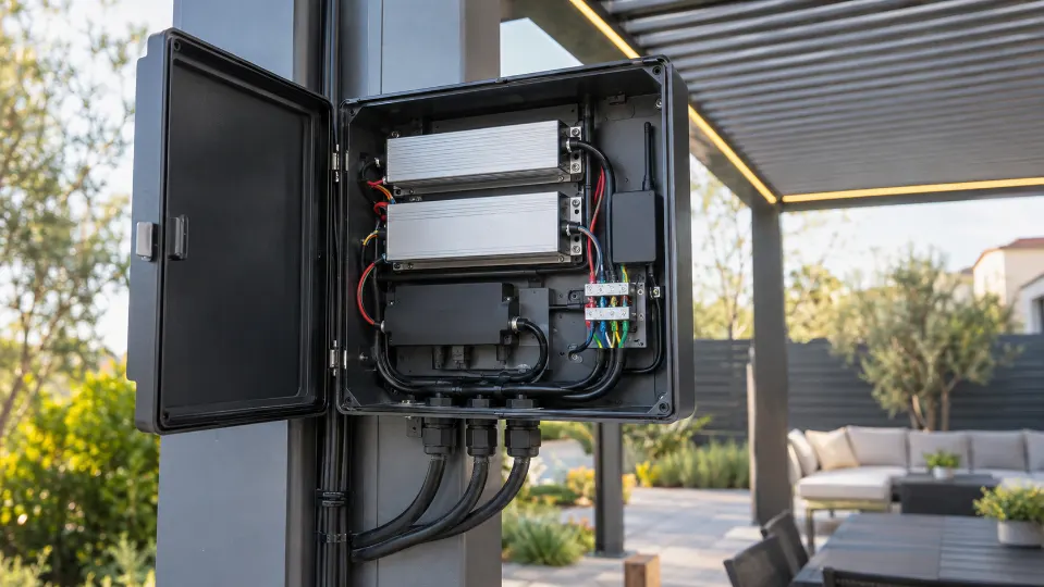
Keep water management visible on the wiring diagram
A pergola wiring diagram is incomplete if it shows electrical connections but not the environmental path around them. Water can arrive from direct rain, condensation, cleaning, drainage channels, or capillary action along a cable. A connector listed as waterproof does not make an installation waterproof if it is mounted in a pocket where water remains trapped or if the cable enters the enclosure without a suitable gland or drip loop.
Mark these items directly on the drawing:
- Highest and lowest points in the cable route.
- Drainage channels and areas that must remain unobstructed.
- Connector orientation and any required downward-facing loop.
- Control-box mounting orientation and cable-entry points.
- Separation from moving louvers, link bars, gears, and sharp edges.
- Inspection or replacement access.
For North American projects, the UL Solutions overview of landscape and outdoor lighting is a useful reminder that line-voltage and low-voltage lighting systems are evaluated differently and that power units and luminaires may be assessed as a system or as compatible separate components. The exact compliance route depends on the market, product construction, and installation method.
Draw the control logic as a second diagram
One page should show physical wiring. A second page should show control behavior. Combining both into a crowded drawing makes commissioning harder and hides failure modes.
The control-logic page should define:
- Which remote, app, or wall panel command operates each channel.
- Whether lights are grouped, independently dimmed, or scene-controlled.
- Whether a sensor can override a manual command.
- What happens after a power interruption.
- How the system behaves when a motor reaches a limit or reports an obstruction.
- How the installer pairs, resets, and replaces a controller.
Weather automation deserves special care. A rain sensor may issue a close command, but it does not turn an open roof into a certified weatherproof enclosure. A wind sensor may trigger a protective position, but the threshold, delay, sensor location, and mechanical limits must be validated for the complete pergola. Document the priority order: for example, emergency or protective logic first, manual movement second, lighting scenes independent unless the product specification says otherwise.
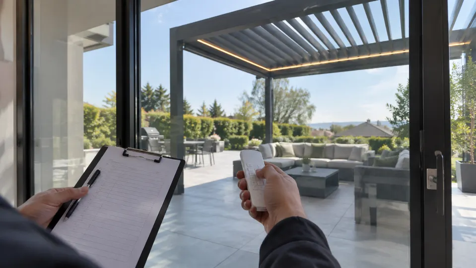
Use a wiring diagram that production and service can both read
The best drawing is not the one with the most symbols. It is the one that lets a production technician assemble the harness correctly and lets a service technician isolate a fault quickly.
For an OEM release package, we recommend four related documents:
- System block diagram: shows supply, controller, motor, lighting, sensors, and interfaces.
- Harness and connector drawing: shows cable lengths, pinouts, keys, labels, and branch destinations.
- Physical routing drawing: shows where cables sit inside posts, beams, louvers, gutters, and control-box cavities.
- Commissioning and fault guide: shows pairing, limit setting, sensor tests, polarity checks, and expected readings or responses.
Assign a revision number to every document and keep the motor model, controller revision, power-supply model, lighting family, and connector system on the title block. This prevents an old wiring sheet from being reused after a component change.
Common diagram mistakes that create field problems
1. Treating every two-wire load as interchangeable
Two wires may represent a DC light, a polarity-reversing actuator, a switched motor input, or a proprietary interface. Label function and voltage, not only wire count.
2. Showing a power supply without its load map
The diagram should identify which outputs feed which fixtures and how the connected load is calculated. A controller limit is not a recommendation to operate continuously at the limit without considering heat, tolerance, and future variation.
3. Routing cables through the drainage path
Drainage and wiring may occupy the same extrusion only when the design intentionally separates them and protects the cable. “There is room in the channel” is not a water-management strategy.
4. Hiding the only service point
A compact control box is valuable only if an installer can reach it, identify it, and replace it. Plan access before the roof and trim are finalized.
5. Omitting the failure state
Document what the system does if the remote is lost, the app is offline, the weather sensor is disconnected, or one motor fails. A premium product should have a predictable recovery path.
OEM wiring review checklist
- Are line-voltage and low-voltage boundaries unambiguous?
- Does every motor output identify the exact motor or actuator family?
- Are lighting voltage, control type, connector pinout, and output limits stated?
- Can every harness be installed without passing through a sharp edge or moving mechanism?
- Are drain paths, cable-entry points, loops, and service access shown?
- Can production identify each branch without relying on memory?
- Can an installer commission the roof and lighting separately?
- Are sensor priorities and power-loss behavior defined?
- Have the drawing revision and component revision been linked to the BOM?
- Has the complete assembly been tested under the target environmental and mechanical conditions?
Design the control platform before you finalize the pergola frame
The control system should influence the frame design early. Reserve a dry, accessible cavity. Confirm the controller’s dimensions and heat conditions. Define whether the power supply is inside the pergola, in a nearby service enclosure, or at the building side. Coordinate cable entry with drainage, corner joints, removable covers, and the movement envelope of the louvers.
This is also the stage to decide whether your product will ship with a standard harness, a pre-installed lighting package, or a configurable kit. VLEDSTAR’s pergola lighting kits and lighting-system portfolio are structured around pre-configured and custom options, including downlight kits, strip-light kits, retrofit profiles, smart controls, drivers, splitters, and connectors. For a manufacturer, that kind of modularity can shorten installation time while keeping the system inside a known electrical envelope.
If your pergola range includes several sizes, do not create a separate improvised diagram for every model. Build a controlled platform: standard connector families, standard cable labels, defined controller variants, and a clear rule for when a larger roof requires another power branch or motor channel.
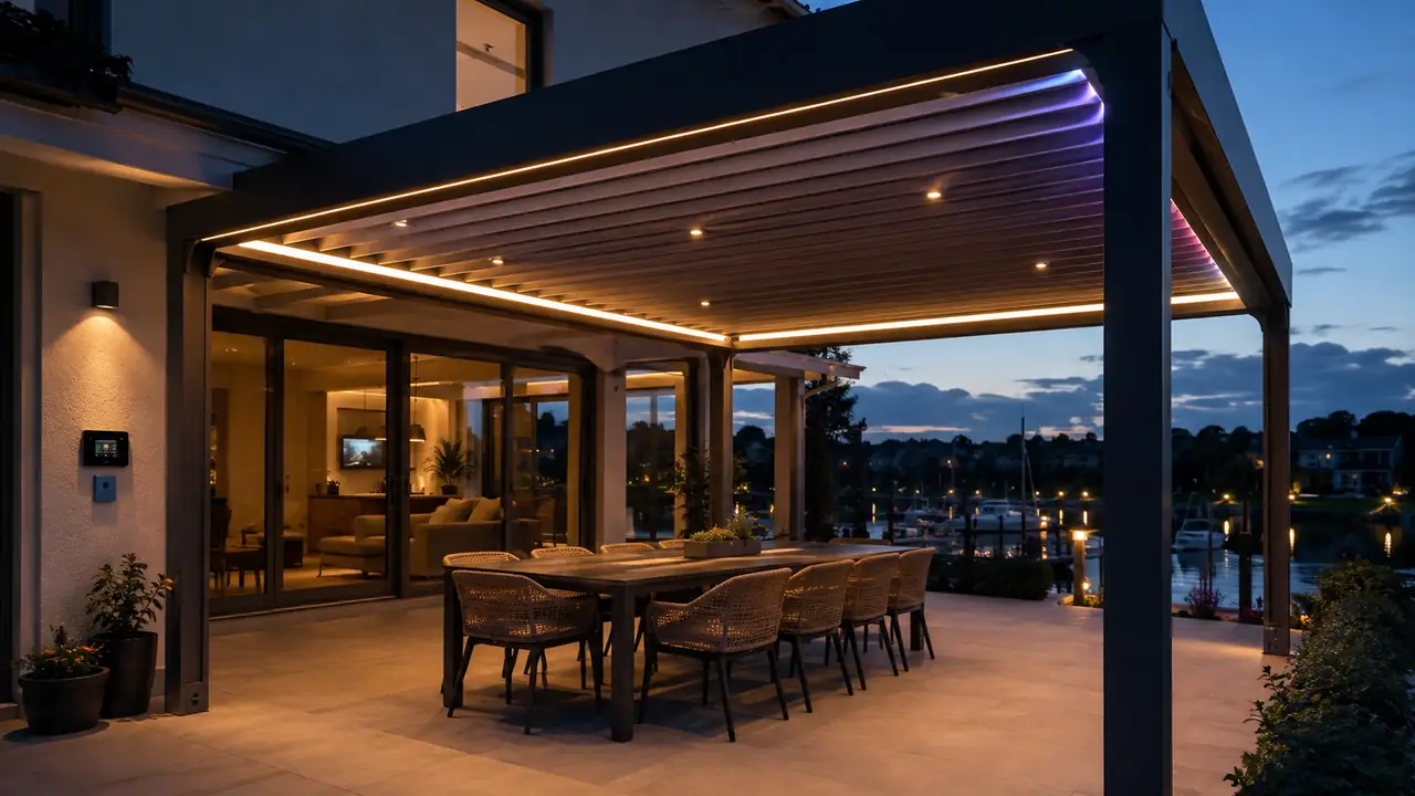
Our position as a lighting and control system manufacturer
We do not see lighting as an accessory that is added after the pergola mechanism is finished. Lighting changes the power budget, cable route, control interface, thermal conditions, service requirements, and customer experience. Motor control changes the safety logic and the commissioning sequence. The product performs best when those decisions are developed together.
At VLEDSTAR, our work covers LED spotlights, strip lights, wall and post lights, power supplies, connectors, complete lighting kits, and integrated control systems for louvered and retractable structures. Our company profile describes our focus on pergola lighting and control-system R&D, manufacturing, and co-development for pergola brands. For an OEM, the value is not a longer product list. It is the ability to align the fixture, harness, controller, motor interface, and production documentation around one buildable system.
Final takeaway
A louvered pergola wiring diagram should make the whole product easier to manufacture, install, commission, service, and upgrade. Start with the architecture. Separate power paths. Identify the motor type. Divide lighting into zones. Show water management and movement clearance. Document connectors and control behavior. Then validate the complete assembly with the exact components that will ship.
If you are developing a new pergola model or replacing a fragmented lighting and motor-control setup, send us the roof layout, motor type, target market, lighting concept, and preferred control method. The VLEDSTAR team can help convert those requirements into a practical lighting and integrated control architecture for your product range. Visit the pergola control system page أو contact VLEDSTAR to discuss the next design iteration.
Build the wiring concept into the product from day one
Share your pergola dimensions, motor architecture, lighting zones, and target market with VLEDSTAR. We will help you evaluate the control topology, lighting branches, connectors, and kit structure before production tooling is locked.
Explore integrated control systems أو review the pergola lighting range.

أرسل لنا طلبك