


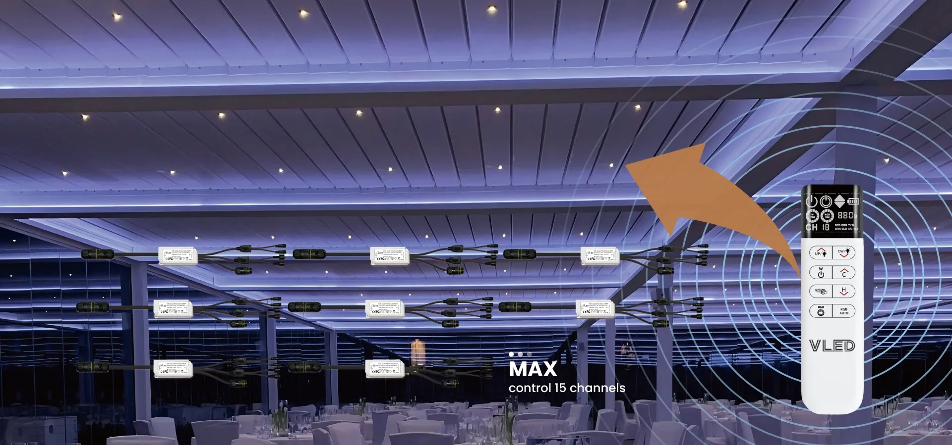
Why 15 zones? How far does 433 MHz RF actually reach on a real job site? What does “multi-zone” really mean to an installer? Answers from the engineering team that built PergoPro — with real customer stories behind every decision.
Ask most pergola lighting suppliers how many zones their controller supports, and they’ll hand you a spec sheet. We’d rather tell you how we arrived at the number — because the story behind it is far more useful to you as a manufacturer or integrator than any bullet-point feature list.
The short answer is that 15 zones emerged from real customer pain. A French installer juggling three separate remotes. An Italian contractor who needed motors, LED strips, roller blinds, and an LCD display on a single platform. A Colombian developer who handed us a 12-item compatibility wish list before we’d even quoted. Those conversations, stacked on top of each other, made multi-zone control impossible to ignore — and they shaped every engineering decision we made on the PergoPro system.
This article unpacks exactly how the system works, what the real-world limits are, and how to deploy it correctly on large pergola projects.
💡 Quick summary for busy specifiers: PergoPro supports up to 15 independent zones from one RF remote, operating on 433 MHz FSK modulation with a reliable control radius of 60 metres in typical pergola installations. Compatible with single-colour LED strips, RGB/RGBW strips, AC motors (including Somfy and Dooya), sensors, and LCD panels — all from one interface.
Why 15 Zones? The Customer Conversations That Drove the Specification
Fifteen is not a round number we picked for marketing appeal. It is the number we arrived at after accumulating enough real-world installation complexity to know where the balance point sits between “covers enough scenarios” and “stays reliably synchronised”.
— Cjg, French pergola installer (early customer conversation)
Cjg’s frustration was a near-perfect encapsulation of what we were hearing across markets. Three remotes meant three pairing processes, three battery replacements, three chances for a signal conflict, and zero integration with any smart-home platform. That is a system architecture problem, not a product problem.
Federico, an Italian contractor, pushed the brief further: he needed a single platform to address electric motors, LED lighting, motorised blinds, und an LCD status panel — each of which had previously required its own dedicated controller. The idea that a pergola manufacturer should have to bundle four separate control systems into a single product was increasingly untenable for premium market positioning.
Then came the Colombian developer, who sent us an actual compatibility list. Thirteen device types. That list confirmed what we already suspected: the ceiling on customer expectations had risen dramatically, and the baseline of a “smart pergola” was being redefined from the ground up.
🏗️ The engineering implication: We could not simply add channels to an existing remote architecture. We needed to redesign around the assumption that a single controller might need to address structurally different device types — dimmable LED drivers, full-colour RGB modules, relay-switched motors — within the same zone map, with zero cross-talk. That was the real design challenge, and 15 zones was the configuration that solved it without compromising synchronisation reliability.
The RF Technology Behind the Range: 433 MHz FSK Explained
Every wireless control system makes a trade-off between range, reliability, and cost. The technology choices we made on PergoPro are direct responses to the failure modes we observed in simpler architectures deployed in aluminium-framed pergola environments.
📡
433 MHz RF with FSK Modulation: Why We Chose It
PergoPro uses 433 MHz radio frequency transmission with FSK (Frequency Shift Keying) modulation. In open-air conditions, the remote achieves a control range exceeding 100 metres. That figure is accurate — but it is also only the starting point of an honest conversation about range.
In a real pergola installation, the signal must pass through or around aluminium extrusions, louvred blades, retractable canopy tracks, and sometimes reinforced concrete posts. Aluminium scatters RF energy in ways that are difficult to predict from a floor plan. In our field testing, signal attenuation in fully enclosed aluminium-channel pergola structures was consistently more aggressive than most installers anticipated.
Our practical recommendation: position all 15 zone receivers within a 60-metre radius of the remote’s operating location. This is a calibrated engineering recommendation based on real-site data — not a product limitation. Installers who plan layouts around the 60 m figure consistently report reliable operation.
FSK vs. AM Modulation: Why the Difference Matters on Site
Many lower-cost pergola remotes use AM (amplitude modulation) for their RF transmission. AM is cheaper to implement, but its reliability degrades in electromagnetically noisy environments — construction sites, commercial districts, and multi-unit residential developments where dozens of devices share the same 433 MHz band.
FSK encodes information in frequency shifts rather than amplitude changes, which means the receiver can distinguish the intended signal even when background RF noise raises the noise floor. In practical terms: fewer missed commands, more consistent synchronised zone responses, and better performance in dense urban installation environments.
For technical background on FSK modulation and its interference-rejection properties, see the Electronics Notes FSK Tutorial. For the European regulatory context of 433 MHz short-range devices, refer to ETSI EN 300 220 (Short Range Devices).
What “Multi-Zone Control” Actually Means: Four Layers of Customer Expectation
When a customer says they need multi-zone control, they rarely mean just one thing. After enough sales conversations we mapped the request into four distinct layers — designing PergoPro to address all four simultaneously is what separated it from a simple channel-expansion product.
Layer 1 — Zone Count
Enough addressable channels to cover the entire installation. For most commercial pergola projects this means at minimum 6–8 independent lighting zones plus dedicated motor channels. PergoPro’s 15-zone architecture covers even complex multi-bay systems without a second controller.
Layer 2 — Device Type Diversity
Customers need to connect single-colour LED strips, RGB/RGBW modules, AC motors, sensors, and LCD display panels — ideally through the same controller. Mixed device types on separate controllers mean separate remotes, separate pairing, and separate failure points.
Layer 3 — Brand Interoperability
Most installation sites already have motors installed. Somfy and Dooya are the two most prevalent brands across the European and Latin American markets we serve. No customer wants to rip out existing hardware. PergoPro is designed to work alongside these systems — not replace them.
Layer 4 — Control Interface Choice
Some end users want an RF remote. Others want smartphone app control. Some commercial projects require BMS integration via Bluetooth or QR-code pairing. PergoPro exposes multiple control entry points so the manufacturer can specify the right interface without product substitution.
Understanding these four layers transformed PergoPro from a “remote with more buttons” into a unified control platform. The CEDIA Technical Reference Library provides useful independent perspective on integration architectures. The KNX Association’s introduction to building automation gives useful context for understanding why open multi-device control standards matter to commercial buyers.
How Customer Feedback Shaped the Product: Three Iterations That Mattered
Product specs on a datasheet represent a point-in-time consensus. The decisions behind them represent accumulated failure modes, customer complaints, and candid conversations. Here are three iterations in PergoPro’s development that changed the product in ways a spec sheet will never tell you.
1. Rebuilding the RGB Colour Gamut After Chilean Market Feedback
The first version of PergoPro’s RGB lighting output was engineered to produce vivid, saturated colours across the full gamut. It passed our internal testing and looked impressive on demo units. Then we sent samples to Chile.
— Chilean pergola manufacturer, sample evaluation feedback
The customer sent us a reference image. It was not saturated primary colours — it was warm amber gradients, dusty rose, soft terracotta. The kind of palette you find in upscale outdoor hospitality environments: atmospheric, not decorative. Our original colour space was optimised for visibility, not mood.
We rebuilt the gamut with lower saturation ceilings and finer granularity in the warm-amber range. The update took two firmware revision cycles. The Chilean client approved on the second iteration — and that feedback has informed every RGB product shipped since.
2. Establishing the 300W Per-Channel Load Standard
Vincenzo, an Italian installer, asked a question that seemed simple on the surface: “My pergola is only 5 metres long. Will one LED strip channel be enough? What if I upgrade to an 8×4 m structure later — can the controller handle it?”
The question revealed that we had never clearly communicated the load capacity per channel in a way that allowed an installer to plan a project from the outset. The ambiguity was creating hesitation at the point of specification.
⚡ The result: We formalised the 300W per-channel load standard across all PergoPro receiver units. A typical 5 m LED strip draws well under 100W; an 8×4 m canopy can be planned to stay within the 300W envelope per zone. This specification now appears on every product datasheet and installation guide we publish.
3. Documenting the Deployment Radius After Field Report Analysis
The 60-metre practical radius recommendation did not appear in the original product specification. It emerged from aggregating installation reports from projects in France, Italy, and Spain, where aluminium-framed structures were producing intermittent control issues that did not occur on our open-air test range.
Rather than describing the phenomenon vaguely as “signal attenuation may occur,” we conducted structured testing in a representative aluminium pergola environment and derived the 60-metre figure from that data. That number now appears in every installation guide, sales consultation, and technical document we produce — because an honest range specification protects both the installer and the product’s reputation in the field.
Is 15 Zones a Ceiling? How to Think About Scalability
Fifteen zones is not a technical ceiling imposed by physics. It is an engineering optimum — the point at which simultaneous zone synchronisation, command latency, and installation complexity are all within acceptable bounds for the deployment scenarios we target.
| Zone Count | Common Use Case | Sync Reliability | Install Complexity | Our Recommendation |
|---|---|---|---|---|
| 1–2 CH | Single residential pergola, basic on/off | ✔ Very High | Minimal | Entry-level only; no future-proofing |
| 5–6 CH | Mid-range residential; small commercial bays | ✔ High | Low–Moderate | Suitable for single-structure installs |
| 15 CH (PergoPro) | Multi-bay commercial pergola; hospitality; mixed devices | ✔ High (within 60m) | Moderate | Recommended sweet spot ★ |
| 16+ CH | Large estate / campus installations | ⚡ Latency risk increases | High | Grouped deployment preferred |
For installations that genuinely exceed 15 zones — large hospitality terraces, multi-structure estate projects — the correct approach is grouped controller deployment: multiple PergoPro units each assigned a logical zone cluster, rather than attempting to address 20+ zones from a single controller. This preserves synchronisation quality, simplifies troubleshooting, and allows zone clusters to operate independently if one controller develops a fault.
🏗️ Deployment rule of thumb: Each PergoPro controller owns one logical area — one pergola bay, one entertainment terrace, one pool deck. When installations span multiple distinct areas, deploy multiple controllers and bridge them into a higher-level automation system (KNX, Zigbee gateway, or home automation hub) rather than expanding a single controller’s channel count beyond its reliable operating envelope.
For guidance on distributed control architectures in large outdoor structures, Lutron University’s lighting control resources offer useful independent perspective. The Zigbee Alliance technical overview is relevant context for integrators evaluating mesh-network alternatives for very large deployments.
Real-World Deployments: Three Customer Scenarios
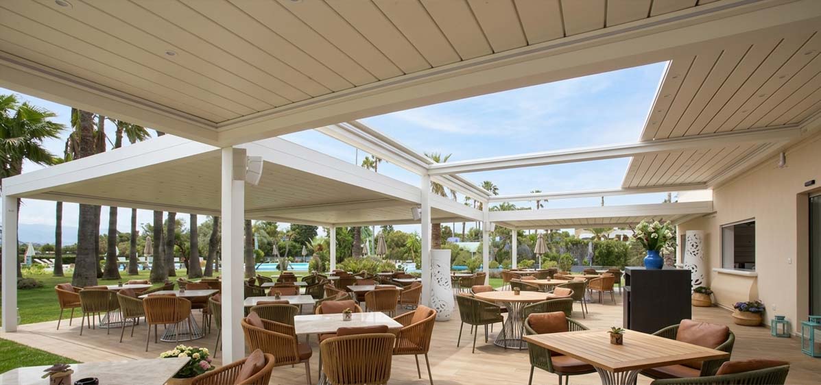
🇫🇷 From 3 Remotes to 1 Controller — Residential Pergola, Southern France
Cjg had installed a pergola system using three separate RF controllers — one for lighting, one for the motorised canopy, one for the outdoor audio relay. Each used a different protocol; none was compatible with his client’s Fibaro home automation system.
After migrating to PergoPro, all three control functions were consolidated into a single 15-zone receiver map and bridged to the Fibaro hub via a Z-Wave gateway relay. The client’s existing home automation scenes (evening mode, rain retraction, party lighting) worked without any additional remote.
Setup time dropped from approximately four hours to under ninety minutes — including the full home automation bridge configuration.
🇮🇹 Mixed Device Integration — Commercial Pergola, Northern Italy
Federico’s project required simultaneous control of four LED lighting circuits, two bi-directional motor channels (Dooya brand, already installed), a retractable screen motor, and an LCD weather-display panel. Previous supplier quotes had required two separate control systems — with no path to integrating the LCD panel at all.
PergoPro addressed all devices within a single 15-zone map. The Dooya motors were paired using the compatible RF learning mode; the LCD panel was assigned a dedicated data channel. All functions were accessible from one remote and one smartphone app profile.
🇨🇴 Developer Specification — Multi-Unit Residential Project, Colombia
A Colombian residential developer presented a specification listing 13 device types across a 24-unit project — each unit with a private pergola terrace, including RGB ambient lighting, single-colour pathway strips, motorised louvres, retractable awnings, and outdoor speaker relay control.
Rather than attempting a single-controller solution per terrace, we recommended grouped deployment: two PergoPro units per terrace (one lighting cluster, one motor/relay cluster), bridged to a central home automation gateway per building block. Each resident has independent terrace control; the BMS can override all pergola states in a safety event.
Commissioning a 15-Zone Installation: Step-by-Step Overview
For manufacturers evaluating PergoPro for integration into their product offering, the commissioning process is a key consideration. Complexity at installation translates directly into support calls and returns.
Zone Mapping
Assign each device (LED circuit, motor, sensor) to a numbered zone on paper first. Verify all receivers will sit within the 60m operating radius.
Receiver Mounting
Mount receivers in weatherproof enclosures, away from aluminium structural members that could cause signal shadowing. IP65 enclosures recommended outdoors.
RF Pairing
Pair each receiver to its assigned zone using the learning-mode sequence. PergoPro supports one-button pairing — under 30 seconds per zone.
Load Verification
Measure or calculate total wattage per channel against the 300W ceiling. For RGB circuits, verify colour calibration matches the intended mood palette before client handover.
App / BMS Integration
Configure the bridge device and test all scenes and override functions from the parent system before client sign-off.
For low-voltage outdoor wiring guidance, US installers should reference NFPA 70 National Electrical Code (NEC). European installers should reference IEC 60364 (Low-Voltage Electrical Installations). Independent outdoor lighting research is available at the Lighting Research Center at RPI.
Frequently Asked Questions
Can PergoPro integrate with Somfy or Dooya motors we already have installed?
Yes. PergoPro uses a 433 MHz RF learning mode compatible with the standard RTS and DC motor protocols used by Somfy and Dooya products. During commissioning, the existing motor receiver enters learning mode and is paired to a dedicated PergoPro zone channel. No wiring modification is required. Installers should verify the specific motor generation is RF-learnable, as some older Somfy wired-only units require an RF adapter bridge.
What happens if one zone loses signal in a 15-zone installation?
Zone communication is independent per receiver — a dropout on Zone 7 does not affect any other zone. The affected receiver retains its last state (on/off/dimmer position) until it receives a new valid command. For commercial installations where zone availability is critical, place all receivers within the 60-metre radius and avoid positioning directly behind load-bearing aluminium columns.
Is 433 MHz RF legal across EU, US, and Latin American markets?
Yes. 433 MHz ISM band operation is legal for short-range devices across the EU (under ETSI EN 300 220), in the US (under FCC Part 15), and across most Latin American jurisdictions following ANATEL or ITU regional frameworks. PergoPro units are CE-marked and FCC-compliant.
Can the number of zones be expanded beyond 15 in future firmware?
The 15-zone limit is an architecture decision, not a hardware bottleneck. Expanding the zone count would require re-validating synchronisation performance at the new channel count — a process we have not yet completed. For projects genuinely requiring more than 15 addressable zones, grouped controller deployment is the validated and recommended approach. We currently have no timeline for an expanded-zone firmware variant.
How do I calculate whether my LED installation stays within the 300W per-channel limit?
Multiply the total length of LED strip on the circuit by the strip’s rated wattage per metre (typically 4–14 W/m depending on strip type). Add any driver overhead. The total should not exceed 270W to leave a safe 10% thermal margin below the 300W ceiling. For example: a 14-metre perimeter circuit using 14 W/m strip draws 196W — well within limits. An 8×4 m canopy approaching 320W total should be split across two zone channels.

Pingback: Integrated Pergola Control Systems: A Manufacturer’s Guide to Louvers, Lighting, and Sensors
Pingback: How to Size 24V LED Drivers for Pergola Beam, Louver, and Strip Lighting Packages
Pingback: Why Pergola Lighting Controls Fail Outdoors and How Manufacturers Can Prevent It
Pingback: How to Control Two Actuators, Two Mono LED Zones, and One RGB Zone from One Pergola Remote
Pingback: Mini LED Spotlight Manufacturer Comparison: What Importers Should Check Before Ordering - miniledspotlight.com
Pingback: How to Differentiate a Pergola Product Line with Custom Control Features