


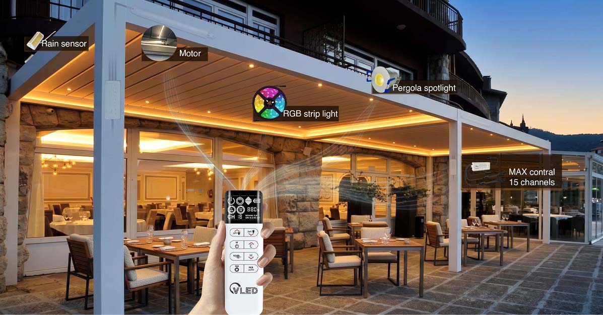
When a smart aluminum pergola worth tens of thousands of dollars has just been installed in a customer’s luxury outdoor space, a remote control that does nothing, or louvers that stall halfway through operation, can cause serious damage to the pergola manufacturer’s brand reputation. Across Europe and North America, electrification and smart control have become irreversible trends in the high-end outdoor living market. Manufacturers now integrate louver drive motors, full-spectrum LED lighting, infrared heaters, and precision environmental sensors into pergola structures. Yet as the density of IoT devices rises sharply, after-sales maintenance data reveals a hard truth: more than half of on-site warranty calls are not caused by damaged tubular motors or mechanical components. Instead, they are system-level failures triggered by RF signal attenuation, electromagnetic interference (EMI), power fluctuations, or control-protocol desynchronization.
Every unnecessary truck roll erodes a manufacturer’s margin. To solve this industry pain point at its root, pergola manufacturers must move beyond a traditional mechanical-engineering mindset and develop a deeper understanding of electromagnetic compatibility (EMC) and RF propagation physics. As a professional manufacturer of pergola lighting and control systems, this article provides a deep engineering breakdown of RF controller troubleshooting, from the electromagnetic shielding effect of aluminum structures to broadband noise pollution from switching power supplies and international spectrum compliance certification. The goal is to provide a complete engineering guide that spans product development and field diagnostics.
RF Physics and the Electromagnetic Conflict in Modern Pergola Structures
Before discussing pairing failures or reduced control range, a smart pergola must first be evaluated within its real physical environment and material-science context. The reliability of an RF control system depends on whether the receiver front end can capture and decode a command signal with sufficient signal-to-noise ratio (SNR) in a complex noise environment. Modern building materials and the pergola’s own structure are often the greatest barriers to RF energy propagation.
The Faraday Cage Shielding Effect of 5052-H32 Aluminum
Modern high-end pergola systems commonly use 5052-H32 marine-grade aluminum alloy as the main structural frame, with Type III hard anodizing or electrostatic powder coating to ensure corrosion resistance in demanding environments such as coastal regions. From a structural-engineering perspective, this material is excellent. From an RF-engineering perspective, however, it can become a massive signal sink.
When a control box, motor receiver, or antenna is fully enclosed inside an aluminum post or canopy cavity, the highly conductive metal enclosure effectively forms a Faraday cage. At the microscopic level of electromagnetic propagation, when an external RF signal — whether a traditional 433.92 MHz signal or a 2.4 GHz smart-home gateway signal — strikes the aluminum surface, the changing magnetic field drives free electrons inside the metal lattice. This creates strong eddy currents, which generate an internal electric field opposite in phase to the incident wave. Most of the electromagnetic energy is reflected back into space or converted into a small amount of heat, causing severe attenuation of any signal attempting to penetrate the metal.
Engineering test data shows that even low-frequency signals with stronger penetration can suffer more than 40 dB of attenuation inside a fully enclosed metal cavity. This means a remote control that would normally reach more than 100 meters in open air may see its effective range collapse to only a few meters, or fail entirely, once the receiver is shielded by an aluminum post. Many installation teams coil the receiving antenna inside a metal control box for aesthetic reasons. In practice, this is equivalent to deliberately severing the system’s wireless nerve.
Building-Material Loss and Multipath Fading
Beyond the pergola’s own metal frame, surrounding building materials also have a decisive impact on the RF link budget. According to ITU-R P.2040-1 from the International Telecommunication Union (ITU) and authoritative testing from the National Institute of Standards and Technology (NIST), different materials absorb and reflect electromagnetic waves in dramatically different ways.
| Interference Medium | RF Attenuation Characteristics and Physical Mechanism | Field Diagnosis and System-Level Response |
|---|---|---|
| Low-E Glass | Coated with a thin layer of metallic oxides such as silver. While this coating blocks infrared heat, it also strongly reflects RF signals, causing severe signal loss of 30 dB to 40 dB. In a 6.75 GHz test, the measured loss reached 33.7 dB. | If users operate an outdoor pergola from indoors through floor-to-ceiling glass and the system does not respond, the glass coating is very likely blocking the signal. Deploy an RF repeater with a high-gain antenna near the indoor/outdoor boundary. |
| Reinforced Concrete Walls | Moisture inside concrete absorbs microwave energy, while the steel rebar mesh forms a secondary Faraday cage, creating severe electromagnetic scattering and absorption loss. | When the smart-home hub is located deep inside the building, evaluate the penetration capability of the 2.4 GHz signal. For long-distance communication through walls, a 900 MHz Z-Wave mesh network should be recommended over high-frequency Wi-Fi with weaker wall penetration. |
| Dense Vegetation and High Humidity | Water molecules in leaves naturally absorb certain frequencies, especially in microwave bands. During rainy seasons, high humidity absorbs energy and may also enter poorly sealed control boxes, changing circuit impedance. | RF failures often show seasonal patterns, such as shorter remote-control range during lush summer growth. During installation, ensure the main receiving antenna has a line of sight that avoids tree canopies, and regularly clean condensation and dirt from the antenna surface. |
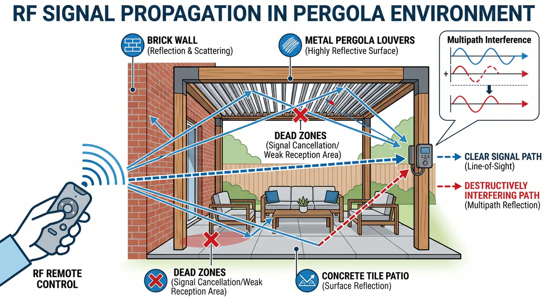
When RF waves bounce repeatedly between brick walls, metal louvers, and patio tiles, they can also create complex multipath fading. The main signal reaching the receiving antenna combines with delayed signals from reflected paths. If the phase of a reflected signal is opposite to the main signal, offset by 180 degrees, destructive interference occurs and forms a signal null. This explains why a remote may fail at one specific point on a patio, then work normally again after the user moves only half a meter.
Hidden Spectrum Killers: LED Drivers and Electromagnetic Interference
After physical obstruction and multipath fading have been ruled out, intermittent loss of control, enlarged dead zones, or extremely slow response should shift the diagnostic focus to the system’s internal electromagnetic compatibility. In a highly integrated pergola ecosystem, the most easily overlooked and destructive RF interference source is often a low-cost or poorly designed LED driver.
Pulse-Width Modulation and High-Order Harmonic Radiation
Modern pergolas are often equipped with dimmable ambient lighting systems. To achieve efficient dimming, LED drivers usually use switch-mode power supplies (SMPS) and pulse-width modulation (PWM), rapidly switching current on and off at high frequencies from 20 kHz to 100 kHz.
From a signal-analysis perspective, this rapid voltage switching appears on an oscilloscope as a steep square wave. According to Fourier series expansion, an ideal square wave contains not only its fundamental frequency energy but also countless odd-order high-frequency harmonics. If the driver’s PCB layout is poorly optimized and lacks sufficient input chokes, common-mode filters, or X/Y capacitors, these high-frequency harmonics can couple directly into the long power cables running through the pergola. At that point, the AC or DC power wiring throughout the frame becomes a giant unintentional transmitting antenna, radiating broadband electromagnetic noise across 20 kHz to 100 MHz and even higher frequency bands.
Receiver Desensitization and the Power-Down Test
This intense RF noise is invisible, but it directly raises the electromagnetic noise floor around the receiving antenna. When the background noise energy exceeds the strength of the legitimate signal emitted by the user’s remote control, the receiver’s low-noise amplifier (LNA) becomes saturated. In RF engineering, this phenomenon is known as receiver desensitization.
During field troubleshooting, technicians should use the power-down test as a standard diagnostic method. The procedure is simple: when the environmental noise floor is at its highest, usually at night with all lighting turned on, temporarily disconnect power to all LED strips and drivers. If the motor’s remote-control range instantly returns to the factory-rated level, or static noise on an AM/FM radio suddenly disappears, the LED driver can be confirmed as the interference source.
The fundamental solution to this type of EMI problem is supply-chain improvement. Manufacturers must move away from low-cost, unfiltered drivers and adopt high-quality power modules with built-in EMI line filters, such as Schaffner filters. For already installed systems affected by interference, technicians can clamp high-permeability ferrite cores onto LED power cables and motor-control lines. Their high impedance at RF frequencies converts conducted interference into small amounts of heat, quickly cleaning up the electromagnetic environment.
Power and Logic: Deep Diagnostics and Troubleshooting Workflow
Once the electromagnetic environment is understood, technicians facing a completely unresponsive pergola controller should follow a strict system-level diagnostic protocol. More than 70% of pseudo-failures do not require replacing an expensive motor assembly; they can be resolved through logic reset and power correction.
Physical Layer Basics: Battery Chemistry and Power Integrity
Battery depletion is the most common and most easily overlooked cause of a broken communication link. Remote controls usually rely on 3 V CR2032 or CR2430 coin cells to provide transmission power. It is important to note that even if the LED indicator on the remote still flashes when a button is pressed, this does not prove the battery is healthy. At the instant the remote transmits an RF pulse, an aged battery may suffer a severe transient voltage drop due to slower internal electrochemical response, leaving the transmitter without enough power to penetrate even thin glass.
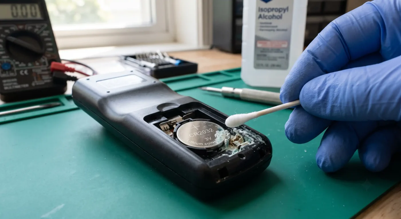
Extreme outdoor temperature swings, especially winter cold, can also reduce lithium battery activity significantly. Technicians should instruct users to remove the battery and carefully inspect the metal contacts inside the battery compartment. White or green oxidation indicates moisture-induced electrochemical corrosion. Cleaning the contacts with isopropyl alcohol and a dry cloth, then installing a high-quality new battery, often restores the remote immediately.
For systems powered by hardwired DC supply, technicians must use a digital multimeter to test voltage stability at the transformer output. Long outdoor cable runs can easily cause voltage drop. When the supply voltage hovers near the operating threshold of the microcontroller (MCU), the RF decoder chip may show highly unstable intermittent failures.
Logic Control Layer: Thermal Protection, Reset, and Travel Calibration
When the power link is intact but the motor still refuses RF commands, the diagnostic focus must move to the system’s internal control logic and safety protection mechanisms.
To extend service life, professional tubular motors such as Somfy or Rollease Acmeda integrate thermal protection sensors inside the stator windings. During repeated commissioning at initial installation, if the motor runs continuously for more than 3 to 4 minutes, the thermal element may trigger and forcibly cut off the main control circuit to prevent insulation damage. In this state, the motor remains silent to all RF commands. Technicians do not need to panic. Let the system cool for 15 to 20 minutes; once the thermal switch resets automatically, normal RF response will return.
If the motor emits a faint beep or only makes a small jog but refuses to complete a full movement, this usually means the travel-limit data in non-volatile memory (NVRAM) has been lost, or the pairing key has been corrupted. During system programming, if the upper open limit and lower closed limit are accidentally set too close together or even overlap, the microcontroller’s logic may fall into a contradiction — such as “the current position is already at the lower limit, so a down command is rejected.” The visible symptom is a system that appears frozen.
The only reliable way to repair this type of logic deadlock is to perform a hardware-level factory reset. Using the industry-standard Somfy RTS system as an example, technicians must execute the strict 2-10-2 power-cut sequence: disconnect motor power for 2 seconds, restore power for 10 seconds, disconnect again for 2 seconds, then restore power. The motor will jog to confirm the reset and clear redundant internal data. The technician should then press and hold the UP and DOWN buttons on the remote simultaneously to start pairing, and after motor confirmation, recalibrate the physical limits of the louver opening and closing range.

Sensor Control Layer: Environmental Adaptation and Safety Override
A modern smart pergola is not an isolated shade device. It is a closed-loop system with environmental awareness. To prevent hurricanes from tearing louvers apart or heavy rain from backflowing into the structure, systems are usually connected to anemometers and optical rain sensors. When environmental parameters exceed safety thresholds, the control logic triggers the highest-priority sensor override, forcibly retracting or protecting the pergola and temporarily blocking all user RF commands.
However, if the weather is clear and windless but the pergola frequently enters self-protection mode and rejects remote control, the sensors must be physically inspected. If cobwebs, leaves, or fine grit become wrapped around the rotating bearing of an anemometer, the internal Hall element may generate high-frequency false pulses, causing the system to misjudge the situation as strong wind. Adjusting the sensor sensitivity potentiometer and gently cleaning the mechanical structure with compressed air can remove this confusing logic lockout.
Breaking Physical Barriers: Antenna Engineering and Network Architecture Upgrades
Fixing existing faults is only the foundation of after-sales service. For pergola manufacturers, true competitiveness lies in using rigorous RF hardware design to eliminate potential communication bottlenecks before the product leaves the factory.
Precision Antenna Deployment: Avoiding Parasitic Resonance
The antenna is the bridge between digital logic and physical space. When the control PCB must be placed inside an aluminum pergola cavity, the physical layout of the antenna determines the success or failure of the entire system. The antenna must never be casually coiled and sealed inside a metal box with the control board, as this causes RF energy to oscillate and dissipate inside the enclosure.
Correct engineering practice is to route the antenna to a non-metallic area and strictly follow spacing rules. According to RF design principles from the IEEE, the receiving antenna must maintain an absolute physical distance of at least one-quarter wavelength from any parallel metal structure, such as a pergola main beam. If the antenna element accidentally touches a conductive metal bracket, even at a point as small as a needle tip, the entire metal frame becomes a giant parasitic element. This not only completely changes the antenna’s radiation pattern but also causes severe characteristic-impedance mismatch, destroying the signal-capture capability the system was designed to achieve.
For hardware selection, if the antenna is mounted directly on the surface of a metal control box, the metal enclosure can act as an ideal ground plane. In this case, a quarter-wave monopole antenna can provide a good voltage standing wave ratio (VSWR). If coaxial cable must be used to extend the antenna away from obstructions, a half-wave dipole antenna should be used instead, because it has independent resonance characteristics and does not rely on a ground plane to achieve higher receive gain.
Evolution from Point-to-Point Control to Mesh Networks
For large commercial outdoor spaces covering thousands of square feet, simply increasing transmission power to overcome physical barriers is both unstable and likely to violate radio regulations. The more robust solution for complex topologies is a mesh network architecture based on Zigbee, Z-Wave, or Thread.
In traditional 433 MHz point-to-point communication, once a concrete wall blocks the link between the main controller and the pergola, the connection can collapse immediately. In a mesh architecture, every smart landscape light, heater controller, and indoor gateway in the outdoor environment can also serve as a signal relay router. When the main control signal encounters a metal obstruction, the network protocol dynamically calculates an optimal multi-hop path around the obstacle and relays the command to its final destination. This self-healing RF network architecture greatly improves system robustness and is an essential foundation for high-end pergola control systems.
Cross-Border Compliance Traps: FCC and CE Certification
Solving RF interference and communication issues is not only a technical challenge. It is also a major compliance risk for every export-oriented manufacturer. International markets regulate radio spectrum extremely strictly, and pergola designs that lack compliance awareness can suffer catastrophic setbacks during customs clearance.
Risk Areas in the U.S. FCC Certification System
According to U.S. Federal Communications Commission (FCC) requirements, all electrical and wireless components inside a pergola must undergo strict review. Customs data shows that about 12% of smart wireless products are directly detained or destroyed because FCC documents are missing or falsified.
Manufacturers must clearly classify product components and apply the correct test standards. Unintentional Radiators — including DC motors and LED drivers with switch-mode power supplies — do not intentionally transmit wireless communication signals, but they generate RF noise as a byproduct of high-frequency operation. They must comply with FCC Part 15 Subpart B. Manufacturers must commission an ISO/IEC 17025 qualified laboratory, such as an A2LA- or NVLAP-accredited facility, to conduct conducted-emission and radiated-emission tests and issue a Supplier’s Declaration of Conformity (SDoC). If a manufacturer removes an EMI filter to save a few cents and the device exceeds FCC Class B residential emission limits, it may interfere with neighboring devices and face substantial federal fines.
Intentional Radiators — including components such as RF remote controls, Bluetooth modules, and Wi-Fi hubs — actively emit electromagnetic waves and are governed by the stricter FCC Part 15 Subpart C. Manufacturers cannot rely on self-declaration. They must submit detailed RF test data to a Telecommunication Certification Body (TCB) for formal approval and obtain a unique FCC ID.
Many manufacturers make a critical mistake: they assume that purchasing an off-the-shelf wireless module with an FCC ID and soldering it onto the main control board is enough. In reality, if the manufacturer changes the antenna type, adds an RF amplifier, or encloses the module in an unevaluated housing during integration, the original FCC approval can become invalid immediately. During customs inspection, if the product packaging or nameplate lacks the correct FCC ID marking, the shipment may be automatically detained. These basic labeling mistakes account for a large share of customs rejections.
Dual Standards Under European CE Certification
For pergola products exported to Europe, manufacturers cannot simply reuse U.S. test reports. If U.S. customs officers see only a CE mark, they will still require documentation specific to the U.S. market, and the reverse is also true. Under the CE framework, in addition to general electromagnetic interference and immunity standards such as EN 55032 and EN 55035, pergolas with integrated LED lighting systems must also pass EN 55015, the dedicated RF emission standard for lighting equipment.
Smart manufacturers introduce spectrum analyzers early in the R&D cycle during the pre-compliance phase and perform whole-system sweep testing in an anechoic chamber. Adding PCB ground copper area and placing ferrite beads on critical lines early in the design process is far more economical than recalling products and remaking tooling after certification failure in mass production.
Conclusion and Call to Action
In today’s highly connected world, the value of a smart pergola has moved far beyond the physical weight of its aluminum alloy. When customers press a remote-control button, they expect a seamless, instant, and refined experience. Yet remote-control failure, response delay, and signal dead zones are not isolated events that can be dismissed as “just a dead battery.” They are the inevitable result of structural shielding from 5052-H32 aluminum, high-frequency broadband pollution from LED switching power supplies, and mutual interference across today’s dense RF spectrum.
Pergola manufacturers must recognize that the transition from traditional mechanical-component maker to smart-space integrator requires more than excellent metal fabrication. It also requires deep respect for RF integrity and electromagnetic compatibility. Every cost compromise made on low-grade electronic components can return many times over in after-sales support costs and lost brand trust.
By adopting RF modules pre-certified under strict FCC/CE requirements, deploying industrial-grade EMI-resistant filter architectures, and integrating self-healing mesh networking technology, you can eliminate the control failures that frustrate customers. As a professional manufacturer of pergola lighting and control systems, we understand the extreme complexity of outdoor RF environments. We provide not only hardware, but also underlying RF solutions proven under both laboratory testing and harsh climate conditions. Contact our RF engineering team today and bring professional EMC design into the DNA of your next-generation pergola. In the invisible turbulence of electromagnetic waves, we help protect the strongest foundation of your brand.

Pingback: Come i produttori di pergole possono sostituire i telecomandi separati con un unico sistema integrato di controllo dell'illuminazione e delle lamelle
Pingback: Posizionamento del sensore di pioggia per tetti a lamelle motorizzati: linee guida del produttore e dell’installatore