


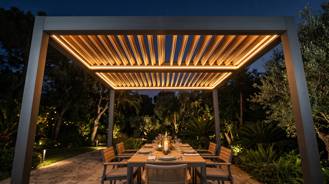
Outdoor architectural structures are undergoing a profound paradigm shift. From traditional timber shade structures to today’s highly engineered aluminum bioclimatic pergolas, consumer expectations for outdoor living spaces have risen to the level of premium indoor residential experiences. Along this path of evolution, the lighting system is no longer an afterthought or an add-on accessory. It has become a core engineering module that defines the overall aesthetics, functional depth, and final profit margin of the pergola.
Yet many European and North American original equipment manufacturers, or OEMs, still treat integrated lighting systems as a simple combination of wires and bulbs. When these systems are deployed in extreme outdoor environments — such as the high salt fog of Florida, the high heat of Arizona, or the severe cold of Northern Europe — and must also face stringent North American electrical code requirements, consumer-grade or non-custom lighting solutions often expose fatal weaknesses very quickly: thermal failure, flicker, voltage drop, and blocked compliance pathways. This report analyzes the low-level logic of pergola LED lighting in driver sizing, thermal derating, protocol-level dimming, and channel control, providing OEMs with a systematic blueprint for building an industrial-grade plug-and-play architecture.
Chapter 1: Driver System Architecture — The Physical Contest Between Voltage and Current
The LED driver is the heart of the entire lighting ecosystem. It is responsible not only for energy conversion but also for serving as the first line of defense against grid fluctuation and lightning surge. At the initial stage of system design, OEMs must make an irreversible strategic choice between constant-voltage (CV) and constant-current (CC) topologies.
1.1 The Essential Difference Between Constant-Voltage and Constant-Current Topologies
Light-emitting diodes (LEDs) have nonlinear voltage-current (V-I) characteristics. As semiconductor junction temperature rises, the LED forward voltage (Vf) decreases. If an LED is connected directly to a constant voltage source without any current-limiting measures, current will rise exponentially, eventually causing thermal runaway and chip burnout.
In practical pergola lighting applications, the industry has evolved two distinct driver strategies:
Constant-voltage (CV) systems are the dominant choice for pergola main lighting, such as linear light strips embedded in louvers or rain gutter channels. These strips integrate current-limiting resistors or miniature constant-current ICs on flexible printed circuit boards (PCBs). The driver only needs to output a stable 12 V DC or 24 V DC voltage. Because a 24 V DC system halves current at the same power level, it significantly reduces voltage drop and supports longer single-run installation distances — often more than 10 meters — making it the standard configuration for large OEM structures.
Constant-current (CC) systems are mainly used for high-power downlights integrated into posts or beams, as well as architectural spotlights such as the Trex Aura 4 W and 12 W product lines. These fixtures have no internal current-limiting components. The driver must accurately output the forward current required by the LED chips — such as 350 mA, 700 mA, or 1050 mA — while voltage floats within a specified range to match the load.
If these two systems are confused in an OEM factory configuration — for example by connecting a 24 V CV driver to a 700 mA CC downlight — the fixture will be punctured and destroyed instantly. Therefore, modern OEM wiring harness design must enforce separation at the physical connector level, such as by using M12 waterproof plugs with different keying.
1.2 Driver Capacity Planning and Headroom
After the topology is determined, the accuracy of capacity calculation directly affects the system lifecycle. The most basic load calculation formula is:
Ptotal = L × Pmeter
where L is the length of the light source and Pmeter is the rated power per meter.
However, a driver whose paper specifications match at laboratory room temperature will inevitably face challenges in real outdoor applications. If core components such as electrolytic capacitors operate at 100 percent full load for long periods, their equivalent series resistance (ESR) rises rapidly, causing serious heating and shortening mean time between failures (MTBF). Therefore, professional practice requires adding 20 to 30 percent power headroom above the basic load. For systems that frequently face extremely cold starts or need to connect complex smart-control modules, a higher headroom factor should be selected.
The following table shows recommended driver-selection benchmarks for high-quality 24 V DC linear light strips at different lengths:
| Light Strip Power Density (24 V DC) | Continuous Run Length | Theoretical Load | Min. Safe Headroom (20%) | Recommended Industrial Driver Rating |
|---|---|---|---|---|
| 4.8 W/m | 10 m | 48.0 W | 57.6 W | 60 W |
| 9.6 W/m | 6 m | 57.6 W | 69.1 W | 75 W or 80 W |
| 9.6 W/m | 10 m | 96.0 W | 115.2 W | 120 W or 150 W |
| 12.0 W/m | 8 m | 96.0 W | 115.2 W | 120 W |
| 14.4 W/m | 10 m | 144.0 W | 172.8 W | 185 W or 200 W (e.g., MEAN WELL HLG-185H) |
It is worth noting that high-end drivers with active power factor correction (active PFC) may see their PF value fall below 0.9 when the load is lower than 50 percent of the rated value, potentially causing harmonic violations. Therefore, excessive oversizing — such as configuring a 240 W driver for a 40 W load — is also a negative example in engineering design. The system should remain within the optimal 75 to 90 percent efficiency and PF operating range.
Chapter 2: Thermal Derating and Extreme Outdoor Protection
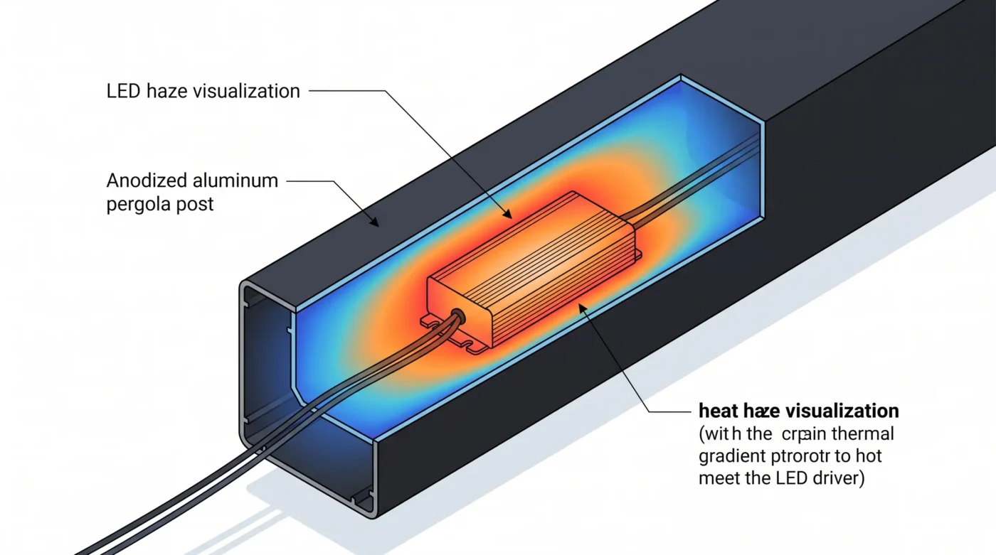
The physical structure of pergola products means that drivers are usually hidden inside black or dark-gray aluminum posts, beam cavities, or waterproof boxes at the top. Under direct summer sunlight, the interior of these sealed metal cavities behaves like a greenhouse.
2.1 The Backlash of High Temperature on Power Electronics
When the internal ambient temperature (Ta) climbs to 60 °C or even higher, thermal derating becomes the only rule that determines system survival. No semiconductor or power device can maintain its nominal output power at high ambient temperatures.
Take industrial-grade outdoor power supplies as an example. Even when they use aluminum housings and fully potted internal thermally conductive silicone for free-air convection, their datasheets still clearly specify derating curves. When ambient temperature exceeds 50 °C, output power must decrease linearly with temperature. At 70 °C, the maximum allowable load may be only 60 percent of the nominal value.
If an OEM ignores the derating curve and operates the driver at full load in high-temperature environments such as Texas or Dubai, the internal temperature-detection circuit of the power supply will trigger thermal shutdown (TSD), causing the pergola lighting to suddenly turn off. In low-quality power supplies without TSD protection, overheating can directly cause capacitor rupture and fire risk.
2.2 Dynamic Thermal Management Algorithms at the LED Chip Level
Not only power supplies require derating; LED light sources themselves are extremely temperature-sensitive. High temperature causes luminous flux depreciation, accelerated phosphor aging, and color-coordinate shift within the MacAdam ellipse. High-end controller manufacturers use negative temperature coefficient (NTC) or positive temperature coefficient (PTC) thermistors together with advanced driver chips — such as Allegro series devices — to achieve dynamic thermal feedback control.
NTC thermistors are usually mounted in the hottest core area of the LED aluminum substrate. When local temperature exceeds a set safety threshold — for example 100 °C — the NTC resistance drops sharply. This analog signal is transmitted to the analog dimming pin (ADIM pin) of the driver IC. After receiving the signal, the driver reduces the forward current to the LEDs according to a specific logarithmic derating curve, in a way users do not notice — slowly and smoothly transitioning from 100 percent brightness to 80 percent. This locks junction temperature firmly within the safe operating area. Such a closed-loop dynamic thermal management system is the key to pushing LED service life to 50,000 or even 100,000 hours.
2.3 Physical Protection: Surge Resistance, Waterproofing, and Corrosion Resistance
Transient grid surge caused by outdoor thunderstorms is another major culprit that destroys control boards. Drivers designed specifically for outdoor municipal and pergola applications — such as HLG or ELG series products — must reach line-to-ground and line-to-line surge ratings of 4 kV or even 6 kV. In terms of ingress protection, IP65 can only defend against low-pressure water jets. When facing severe internal condensation caused by day-night temperature differences, fully potted equipment rated IP67 or even IP68 — with no external adjustment potentiometer holes — is the only viable long-term solution.
Chapter 3: North American Compliance Barriers and a Deep Look at NEC Article 725
For the U.S. market, engineering design is not only a physical problem but also a rigorous legal and compliance issue. The Национальный электротехнический кодекс (NEC) mandates installation standards for all low-voltage and signal wiring. If the electrical architecture of an OEM product has not passed UL certification or violates NEC requirements, the project site may face a red-card rejection from the AHJ, the authority having jurisdiction.
NEC Article 725 specifically sets detailed constraints for remote-control, signaling, and power-limited circuits. It is the reference standard that pergola OEM engineers must master.
3.1 The Strategic Value of Class 2 Circuits
Under Article 725, low-voltage circuits are divided into Class 1, Class 2, and Class 3. Among them, Class 2 circuits are the gold standard for pergola systems. The core definition of Class 2 is that, by limiting voltage and power, it eliminates fire and electric-shock risks at the source, making the circuit inherently safe. To constitute a Class 2 circuit, the power must come from a Class 2 supply compliant with UL 1310 or UL 62368-1, and its output limits are extremely strict:
Maximum DC voltage: no more than 30 V for flicker-free DC systems, or 150 V for special systems.
Maximum output power: strictly limited to 100 VA (watts).
Achieving Class 2 status gives OEMs major cost-reduction and deployment advantages. Because there is no fire hazard, Class 2 wiring does not need to be placed inside bulky metal or PVC conduit, nor does it require a licensed high-voltage electrician for on-site wiring. Pergola assembly workers only need to route wiring inside the profiles and connect it directly with aviation plugs to complete NEC-compliant electrical installation.
| Circuit Class (NEC) | Typical Voltage Limit | Power Limit | Conduit Requirement | Applicable Cable Types | Rules for Mixing with Power Conductors |
|---|---|---|---|---|---|
| Class 1 | 600 V | 1000 VA | Mandatory (e.g., rigid conduit) | THHN / 600 V insulation | Only for functionally associated equipment |
| Class 2 | 30 V / 150 V | 100 VA (100 W) | Usually not required | CL2 / PLTC / wet-location rated | Sharing conduit is absolutely prohibited |
| Class 3 | 150 V | Above Class 2 | Usually not required | CL3 / 300 V insulation | Sharing conduit is absolutely prohibited |
3.2 System Zoning Strategy for Breaking Through the 100 W Limit
A large 12 ft × 24 ft louvered pergola with high-brightness RGBW strips around all sides can easily exceed 300 W of total lighting power. If a single 300 W / 24 V driver is used to power the system directly, circuit power will far exceed the 100 VA limit and will legally be forced into Class 1 classification. At that point, the NEC requires 600 V insulation-grade cables such as THHN, and rigid metal conduit throughout the entire run. In addition, Class 1 wiring is absolutely prohibited from sharing the same raceway with Class 2 or communication wiring unless costly permanent physical separation barriers are installed. This would completely destroy the aesthetics and feasibility of internal pergola wiring.
The breakthrough is a multi-channel current-limiting architecture. The professional OEM control-system solution is to use a control matrix with high-power input and multiple independently current-limited outputs. Inside a sealed centralized control box — for example one equipped with a 320 W transformer — the intelligent control board divides output into four independent channels. Each channel uses hardware-level PPTC resettable fuses or precision current-sense amplifiers to lock the maximum current of each circuit firmly below 4 A (24 V × 4 A = 96 W, below the 100 VA threshold). In this way, the system effectively breaks a large load into smaller compliant circuits. All four output branches legally obtain Class 2 status and can travel freely through the pergola frame without constraint.
For wiring that must pass through building walls or enter plenum air spaces and connect to the indoor main electrical panel, CMP or CL2P plenum-rated cables with extremely low smoke generation must be specified. For outdoor runs directly exposed to rain and ultraviolet light, UV-resistant cables with wet-location marking are mandatory.
Chapter 4: Dimming Algorithms, Scene Building, and the IoT Control Stack
After solving the underlying power and compliance problems, the core factor that determines the user’s willingness to pay a premium is the smoothness of human-machine interaction and the ability to integrate with ecosystems. A modern pergola is not only a daytime sunshade; it is also a carrier of emotional value at night.
4.1 PWM Dimming and Flicker-Elimination Technology
In constant-voltage LED systems, controllers mainly rely on pulse width modulation (PWM) to change perceived brightness. The controller rapidly turns the 24 V DC power on and off at a very high frequency, changing the duty cycle — meaning the percentage of high-level time within the full period — to achieve 0 to 100 percent brightness adjustment.
If the PWM frequency is too low — such as below 100 Hz — the human eye perceives obvious flicker discomfort. Even in the 200 Hz to 500 Hz range, where the naked eye may find it difficult to notice, smartphone videos of pergola dinners can show severe black rolling bands, or a strobe effect. A professional pergola control system should set PWM frequency between 2 kHz and 4 kHz and use high-precision 16-bit dimming resolution in the low-brightness range from 0 to 10 percent. Combined with exponential or logarithmic dimming curves that match the human eye’s greater sensitivity to light changes in dark environments, this delivers a true theater-grade stepless fade effect.
4.2 RGBW and Multi-Zone Scene Control Architecture
Lighting for advanced pergolas has long moved beyond a single warm white. Five-wire RGBW strips — red, green, blue, plus an independent white chip — have become the industry standard. It is important to note that pure white light with a high color rendering index (CRI greater than 90) can never be achieved by mixing only RGB primaries. Food appears pale and unappetizing under RGB-mixed light. Therefore, an independent warm-white channel from 2400 K to 3500 K is the baseline requirement for dining-area lighting.
In control logic, multi-zone control is the dividing line between luxury pergolas and ordinary products. If the perimeter light strips, downlights above the dining table, and wall lights at the column heads are all controlled by the same dimmer, the space is filled with flat, unlayered light and may even produce severe glare on reflective surfaces such as poolside finishes. High-end multi-channel receivers allow different light domains to be divided physically or logically:
Zone 1 — Task Lighting: roof downlights at 80 percent brightness and 3000 K color temperature.
Zone 2 — Ambient Wall Washing: RGBW strips on the inner side of the perimeter rain gutter, outputting magenta at 25 percent brightness.
Zone 3 — Path Guidance: base step lights outputting warm yellow light at 10 percent brightness.
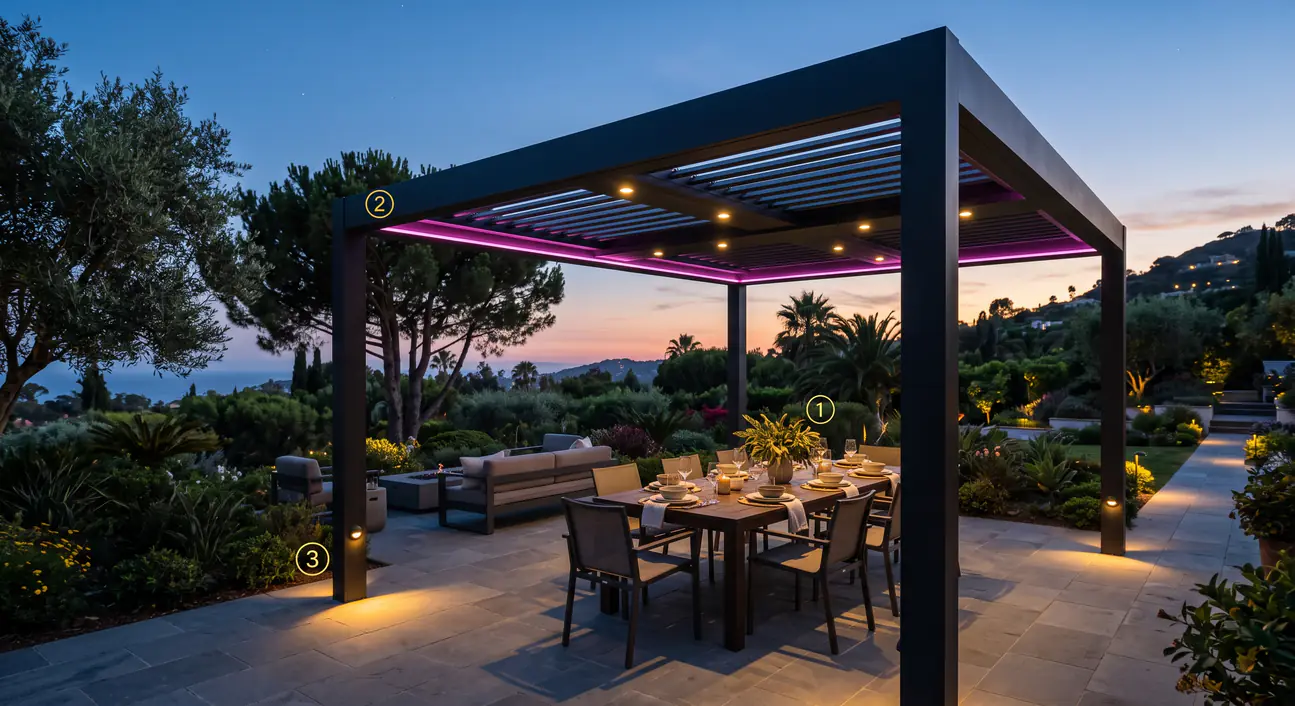
With one tap on “Dinner Scene” in the smart app, the system instantly calls the stored matrix of duty-cycle states for each channel, reshaping the atmosphere of the entire space.
4.3 Protocol Matrix: From Traditional RF to Matter and Casambi
In the competition among low-level communication protocols, OEMs face trade-offs between different technology stacks:
The lowest-cost option, operated through handheld remote controllers. Their limitation is the lack of two-way communication feedback. When blocked by thick aluminum profiles, signal penetration is often poor, frequently causing customer complaints that buttons do not respond.
Currently the preferred architecture for independent high-end lighting in Europe and North America. It does not depend on a home router and can establish a direct network between the smartphone and devices. Each node — whether luminaire or controller — acts as a signal relay, forming a decentralized, self-healing Bluetooth mesh network. Through the Casambi app, users can intuitively control complex RGBW color wheels and scheduled tasks without any subscription fees.
The ultimate vision of whole-home intelligence. Smart pergola controllers launched by Pergolux have already been validated on this stack. These low-power devices based on the Thread protocol can seamlessly access top ecosystems such as Apple HomeKit and Google Home. This means users can set geofencing triggers: when the car enters the garage, the pergola louvers open automatically, the infrared heater turns on, and the lights switch to welcome mode.
Chapter 5: Wiring Harness Topology Optimization and Supply Chain Poka-Yoke Design
Even perfect electrical and control theory becomes a disaster if it cannot be installed correctly by assembly workers without an electrician background on a dusty and muddy construction site.
5.1 Home-Run Star Topology Eliminates Voltage Drop
Pergola lighting wiring often falls into the mistake of daisy chaining — meaning the tail end of the first light strip is connected directly to the head of the second. Because the internal resistance of copper foil conductors accumulates, this wiring method causes serious voltage drop:
ΔV = ( 2 × L × Rwire × I ) / 1000
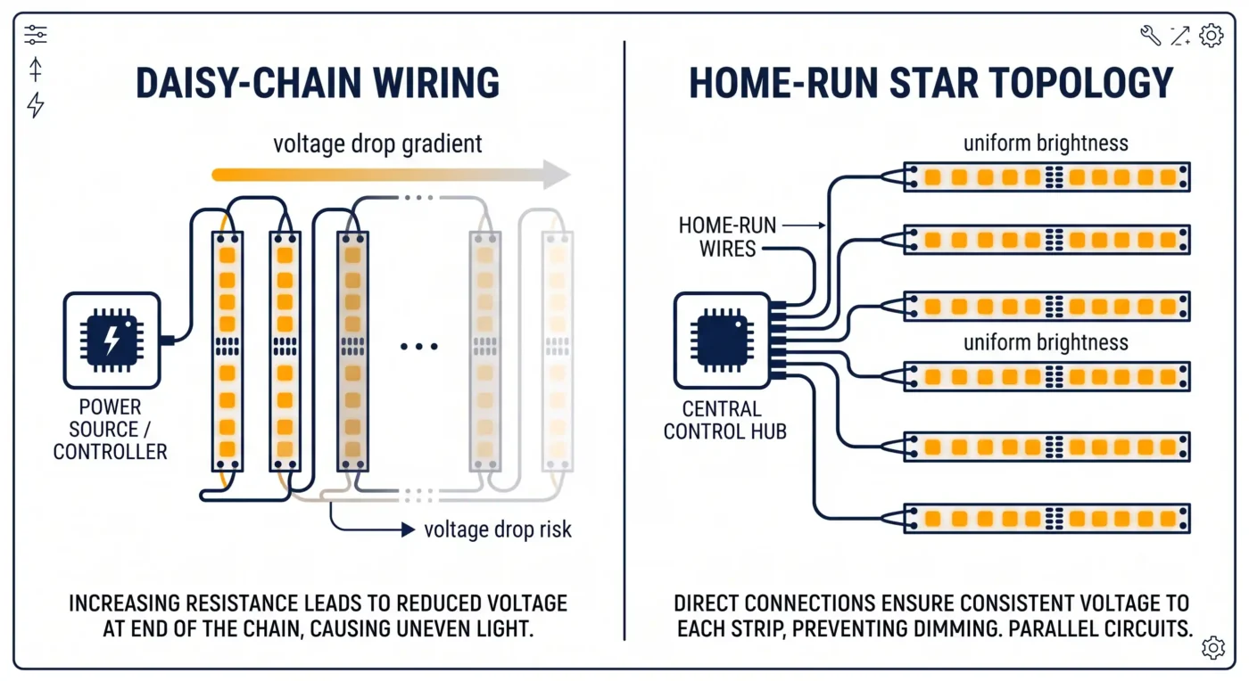
When the voltage at the end of the run drops to 20 V or even lower, white light becomes visibly dimmer, and RGB color shifts badly because blue chips require a higher activation voltage, resulting for example in the white endpoint turning red.
To eliminate this risk, the control system must enforce a home-run star physical topology by design. Whether a light strip is 2 meters or 10 meters from the control box, it must not be connected in series with another strip. Instead, each strip must return directly to a branch port on the central control module through an independent extension cable of appropriate gauge — such as 18 AWG. For large perimeter light strips as long as 65 ft or even 98 ft, strict parallel home-run power feeding is the only path to ensuring color consistency and brightness uniformity.
5.2 Plug-and-Play and Architectural-Grade Sealing
The final expression of an upgraded OEM supply chain is a fully poka-yoke set of prefabricated components:
Eliminate field soldering
All extension wires and light-strip endpoints are spot-welded by automated equipment in a clean workshop and injected with RTV silicone (room temperature vulcanizing silicone) for sealing. On-site wire stripping and heat-shrink operations should be strictly avoided.
IP68 aviation quick connectors
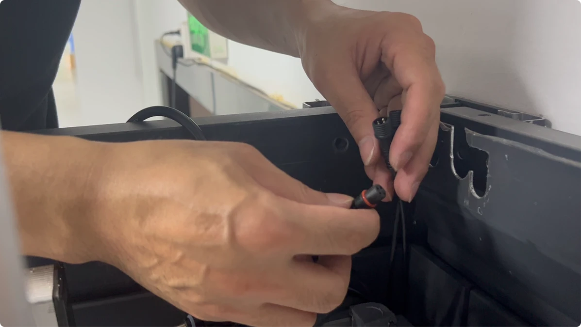
All harness connection ends are upgraded to M12 or quick male-female plugs with threaded locking mechanisms and O-ring seals. Pin definitions are fixed during injection molding, and different light-strip types — such as RGBW 5-pin and pure white 2-pin — use mutually incompatible keyed slots. This fundamentally prevents the risk of wrong connections burning the board.
Flexible extruded profiles
Light strips should not rely only on adhesive backing. They should be embedded into reserved aluminum rain gutters or tracks in the pergola. By covering them with highly weather-resistant flexible silicone or acrylic frosted lenses, manufacturers can eliminate the spotting effect of traditional LEDs and create a seamless, premium light-band effect similar to neon.
Заключение
For European and North American pergola OEMs aiming to establish benchmark status in the global outdoor lifestyle market, LED lighting systems have already moved far beyond simple physical assembly. They involve not only precise matching of constant-voltage and constant-current systems, but also interdisciplinary system engineering that includes extreme thermal derating analysis, NEC Article 725 compliance strategy through Class 2 current-limited zoning, high-frequency flicker-free PWM dimming, and complex IoT ecosystem integration.
Continuing to rely on scattered purchases of generic consumer-grade drivers and unverified dimming modules will not only expose the system to extremely high outdoor failure and customer-complaint risk, but will also greatly compress the product’s premium potential. In a hardware structure market with heavy product homogenization, excellent emotional shaping through light and shadow, together with frictionless smart interaction, is the ultimate tool for building a brand moat.
To gain absolute pricing power in this specialized field, OEM manufacturers must abandon loose, patchwork supply-chain models and turn toward professional system manufacturers with deep electronic-engineering capability, familiarity with strict North American and European compliance standards, and the ability to vertically integrate everything from driver power supplies to smart control and wiring-harness terminals. This depth of joint development and strategic binding is the decisive move for eliminating installation hazards, reshaping product profit structure, and remaining undefeated in the wave of outdoor architectural intelligence.

Пингбэк: Контрольный список комплектующих системы управления перголой для производителей крыш с жалюзи
Пингбэк: Pergola Control System BOM Checklist for OEMs
Пингбэк: How to Size 24V LED Drivers for Pergola Beam, Louver, and Strip Lighting Packages