


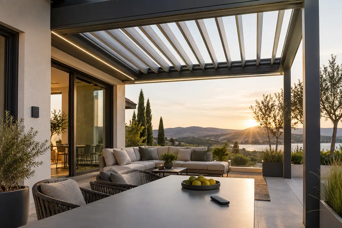
For pergola manufacturers, manual override is often treated as a feature to add late in the specification process. That is a mistake. In a louvered or retractable roof, manual control is part of the system’s safety architecture. It affects motor selection, sensor priority, power-failure behavior, commissioning, service access, user instructions, and the liability carried by the finished product.
The right design question is not, “Can the customer override the automation?” It is, “Which commands should be allowed, under which conditions, and what should the controller do when the system cannot prove that movement is safe?” A well-designed platform gives users practical control without allowing a convenience command to defeat wind, rain, frost, overcurrent, or position protection.
Unsere Position: manual override should be available for normal operation, commissioning, and service, but it should be bounded by a clearly defined safety hierarchy. The controller should fail to a known, conservative state and report why a command was accepted, delayed, or rejected.
Why manual override needs an engineering policy
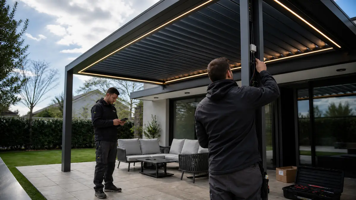
“Manual override” can describe several different functions. A wall switch that has priority over a schedule is not the same as a crank that moves a blind during a blackout. A dealer mode that bypasses a sensor is not the same as a homeowner command from an app. If these functions are described with one vague label, installers and end users will form their own assumptions.
For a manufacturer, those assumptions create avoidable service calls. A homeowner may force a roof against ice because the interface gives no explanation. An installer may wire a local switch in parallel with an automatic weather input and accidentally remove the controller’s ability to enforce a protective state. A hospitality operator may expect a remote command to close every zone, while one motor has lost its limit reference.
A control specification should therefore define at least four forms of authority:
| Command type | Typical purpose | Design question |
|---|---|---|
| Normal user command | Open, close, tilt, stop, dim, or recall a scene | What can the user operate during a weather or fault state? |
| Automatic protection | Wind, rain, snow, frost, overtemperature, or overload response | Which conditions must take priority over a user command? |
| Commissioning mode | Addressing motors, setting limits, checking direction, and testing sensors | How is elevated access protected from accidental movement? |
| Service or recovery mode | Controlled diagnosis after a fault or power event | How is exceptional access authenticated, logged, and returned to normal operation? |
Manual override should be layered, not absolute
The safest architecture separates “manual priority” from “safety bypass.” A user should be able to stop movement, change a comfortable louver angle, or operate lighting without needing the cloud, Wi-Fi, or a proprietary app. That does not mean the same user command should be able to force a motor through a detected obstruction or defeat a protective lockout.
We recommend a layered policy:
Layer 1: Stop always has authority
A stop command should interrupt an active movement as quickly as the motor and control hardware safely allow. It should be available from the local control, remote, and service interface where those interfaces are present. The system should not require an internet connection to stop a moving roof.
Layer 2: Normal movement is permitted when interlocks are healthy
Open, close, tilt, retract, and lighting commands can run when the controller has valid power, valid limits, and no active protective lockout. The controller should check the state of the relevant motor channel rather than assuming that a previous command completed.
Layer 3: Weather protection can take priority
Wind and precipitation logic should be able to issue an automatic protective command even when the system is being used locally. The exact safe position depends on the roof, screen, actuator, sensor placement, and regional operating conditions. It should be specified per product family instead of copied from a generic “close on wind” rule.
Layer 4: A hard fault blocks movement
Overcurrent, inconsistent limit feedback, motor timeout, loss of sensor validity, or suspected mechanical binding should move the channel into a fault state. A reset should not silently clear a condition that could damage the drive or structure. If an exceptional service override is necessary, it should be deliberate, time-limited, and documented.
This approach gives the dealer and customer useful control without turning the override into a hidden way to defeat the system’s protective logic.
Weather sensors need a priority model
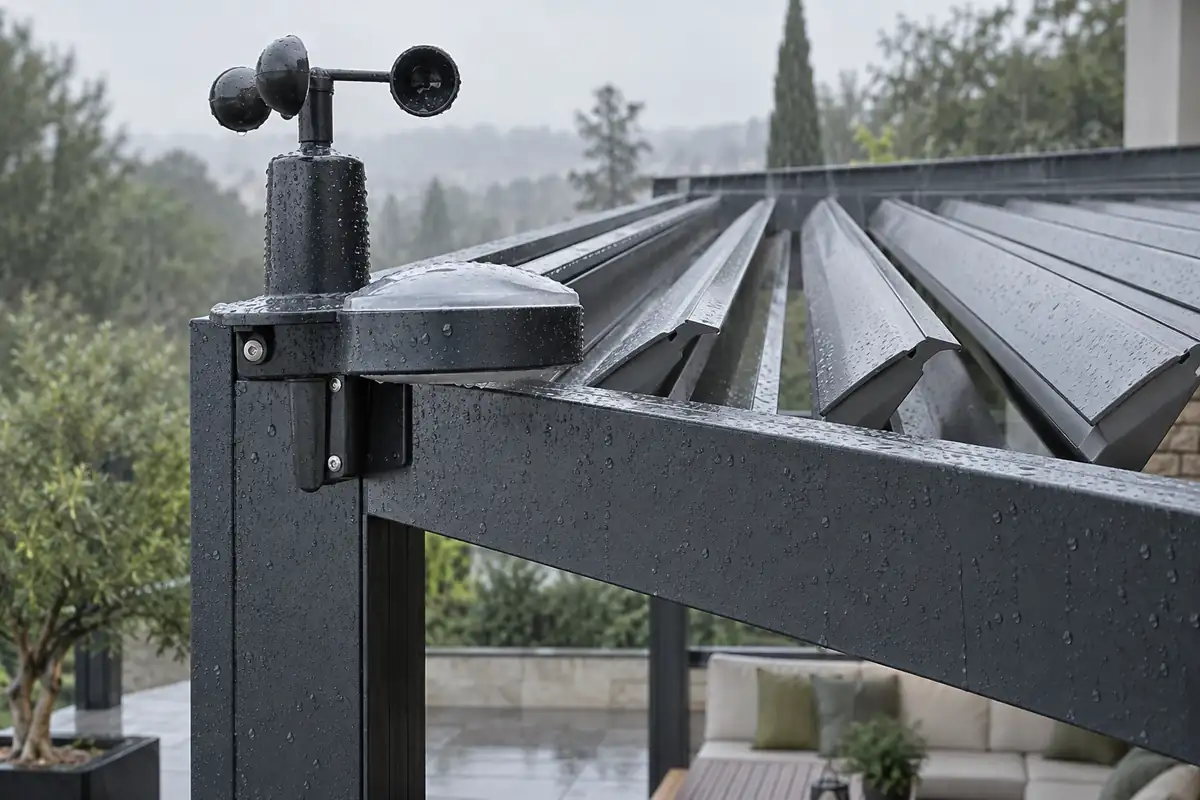
Motorized pergola controls are exposed to weather that can change faster than a user can respond. The controller therefore needs a priority model, not just a collection of sensor inputs. The model should define trigger conditions, the target position, whether movement can be interrupted, the lockout period, and the condition for returning to normal control.
Official documentation for pergola control equipment from Somfy describes wind, rain, and anti-freeze or snow protection as distinct behaviors. That distinction matters. A rain event may call for closing louvers, while wind protection may call for a product-specific position that reduces exposure. A frost condition can require blocking movement because an apparently simple command may be working against ice-bound blades or seals.
For manufacturers, the control logic should answer these questions before the product reaches production:
- Does a weather event interrupt movement immediately, or only after the current cycle finishes?
- Which sensor has priority if wind and rain are detected together?
- What happens if the sensor is disconnected, shorted, saturated, or reporting stale data?
- Can a normal user command clear the lockout, or is a deliberate acknowledgement required?
- Does the controller remember a protective event after a power interruption?
- Does the user receive a plain-language reason when a requested movement is refused?
A good interface does not merely show “not available.” It explains the state: “Movement paused: frost protection active,” “Wind protection position reached,” or “Motor 2 needs service.” Clear feedback reduces unsafe troubleshooting and gives dealers a useful diagnostic starting point.
For a deeper design discussion, see our guidance on wind sensor thresholds for pergolas, rain sensor placement, und snow and frost protection logic.
Power loss: preserve state and prevent unsafe recovery
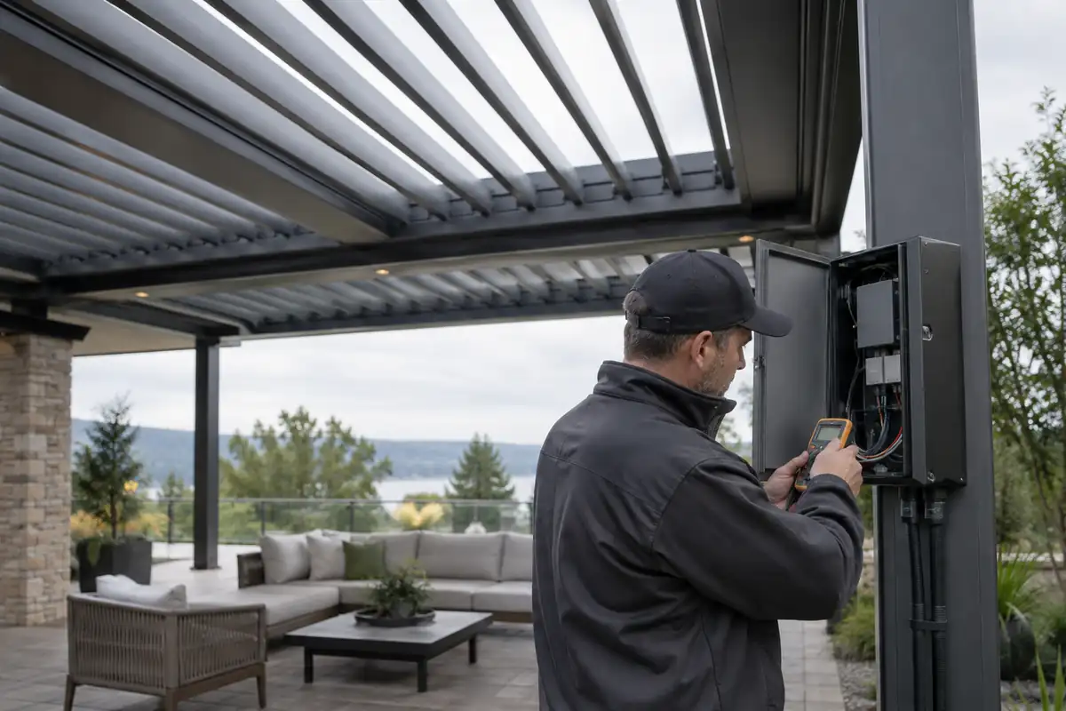
A power outage is not a single failure mode. The motor may stop mid-cycle, the controller may reboot before the motor, the network may remain unavailable, or the roof may return while a sensor input is still active. The most important design decision is what happens when power returns.
Automatic “resume last command” is convenient but risky when the controller has not re-established a trustworthy position. A safer recovery sequence is to initialize outputs, verify sensor and limit status, identify channels with incomplete movement, and then allow only the commands that the current state supports. If position cannot be confirmed, the system should report an unknown or service-required state instead of pretending that the roof is fully open or closed.
Manufacturers should document three separate behaviors:
- During power loss: whether the motor holds, releases, brakes, or can be moved through a mechanical emergency interface.
- At controller restart: whether outputs remain inhibited until the controller completes its safety checks.
- After restart: whether the system restores a scene, waits for a user command, or executes a protective action based on a valid weather input.
Do not promise a manual crank or battery procedure unless the selected motor actually supports it and the mechanism is accessible in the finished pergola. For some systems, the correct power-outage behavior is to hold position and wait for restoration. For others, a screen or shade motor may have a mechanical override. The product manual must describe the real hardware, not an attractive feature list.
Mechanical protection and electrical protection must agree
Software cannot compensate for an actuator that is mismatched to the louver geometry, a linkage that binds at one end of travel, or a screen that is misaligned in its side channel. Fail-safe design begins with the mechanical system and continues through the motor, drive electronics, sensor feedback, and user interface.
At minimum, the controller should supervise:
- Travel limits and direction consistency.
- Run-time or movement timeout.
- Motor current or another reliable overload signal.
- Channel synchronization where several actuators move one roof.
- Unexpected repeated stop-start behavior.
- Sensor validity and communication loss.
A fault response should be conservative but serviceable. Stop the affected channel, preserve the fault reason, allow unaffected lighting or motor zones to remain usable when safe, and provide a clear recovery path. Locking an entire project because one actuator has a fault may be unnecessarily disruptive; allowing every channel to continue without diagnosing a shared power or weather problem is worse.
Enclosure selection also belongs in this discussion. An IP rating is not a general statement that a box is “outdoor proof.” IEC 60529 defines the IP Code as a classification of protection provided by enclosures. The rating, cable entry design, condensation strategy, installation orientation, drainage, and maintenance practice all affect the field result. Our own integrated control platforms use an IP65-rated control box for the intended product configuration, but the installer still has to preserve the enclosure’s protection when mounting and wiring it.
Design the control platform around the OEM product line
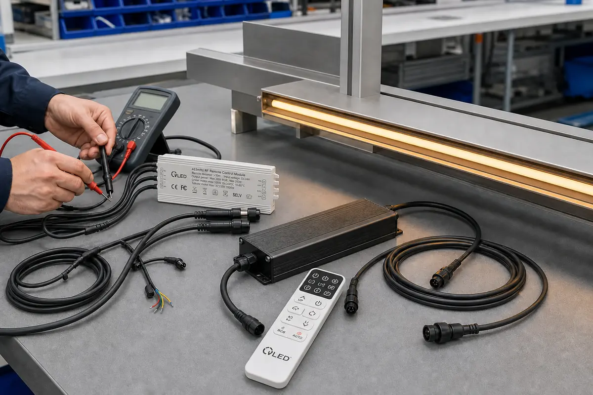
A control box that works in a demonstration unit may still be wrong for a manufacturer. Production needs repeatable wiring, predictable channel assignments, service access, firmware control, compatibility with the selected motors, and a user experience that can carry the OEM’s brand.
VLEDSTAR develops pergola lighting and integrated control systems for manufacturers rather than treating lighting as a separate accessory. Our current control-platform specification supports RGB and mono LED lighting, up to four linear actuators for louver tilt, up to two tubular motors for retractable movement, weather inputs for wind, rain, sun, and snow, and RF remote, Tuya app, and touchscreen control options. The product page for our Pergola-Steuergerät also describes IP65 enclosure protection, 15-channel grouping, and compatibility options for Somfy, AOK, and Dooya motor families. Final compatibility and behavior should always be confirmed against the chosen motor and project configuration.
This integrated approach has a direct fail-safe advantage: the controller can coordinate lighting, louver movement, screens, and weather behavior in one state model. It can also make the override policy consistent across the remote, app, panel, and commissioning tools. When every subsystem has a separate receiver and a separate interpretation of “manual,” the OEM inherits more wiring, more pairing steps, and more opportunities for conflicting commands.
For a new product line, our OEM pergola control platform und integrated control systems guide are useful starting points for defining the hardware and firmware scope. Where a standard platform is not enough, the custom pergola controls workflow can cover channel mapping, enclosure, logo, firmware behavior, and control interfaces.
Validation tests every manufacturer should run
Fail-safe claims should be demonstrated on a complete system, not inferred from a controller data sheet. A practical validation plan can be built around failure injection and recovery:
- Remove mains power during opening, closing, tilting, and retracting. Record the final mechanical state and the state shown by each interface.
- Restore power with the roof mid-cycle. Verify that outputs do not restart blindly and that the controller identifies the incomplete movement.
- Trigger wind and rain inputs separately and together. Confirm priority, target position, interruption behavior, and lockout release.
- Simulate a disconnected or invalid sensor. Confirm that the product enters the documented state and communicates the condition.
- Introduce a controlled mechanical resistance or motor overload within the approved test method. Verify stop timing, fault retention, and service recovery.
- Operate local, RF, app, and touchscreen commands while automation is active. Confirm that every interface follows the same authority rules.
- Repeat the tests across temperature, supply-voltage, and RF-interference conditions relevant to the target market.
For North American products, compliance planning should be discussed with the certification body and the applicable authority having jurisdiction. UL Solutions notes that UL 325 addresses electric operators including louvers, windows, and exterior awnings, with hazards such as electric shock, fire, casualty, and entrapment. The applicable standard, listing path, and installation requirements depend on the actual product and use case; a blog post cannot replace a certification review.
What to put in the product manual and installer handover
Even a technically sound control system can become unsafe when the handover is vague. The installation package should identify the normal control path, the emergency behavior, the weather-protection hierarchy, the meaning of each fault, and the steps that require a qualified technician.
We recommend giving the installer a short commissioning record that captures motor model, wiring, direction, limits, sensor location, protective position, control interfaces, and the result of power-loss testing. The end user should receive plain-language instructions for stopping movement, recognizing a lockout, and contacting service. Avoid telling users to force louvers, defeat a sensor, or repeatedly reset a fault.
The handover is also the right time to explain the difference between a normal override and a service override. If the dealer can temporarily access a diagnostic mode, that access should not be presented as an everyday operating feature. A traceable, role-based service process protects the user, the installer, and the OEM.
Final position: make the safe decision the easy decision
Motorized pergola controls earn trust when they behave predictably under stress. A customer should be able to operate the roof locally when the cloud is unavailable, stop movement without delay, understand why a command was refused, and recover from a power event without guessing. A manufacturer should be able to prove those behaviors across the complete product line.
Manual override is therefore not a checkbox. It is a controlled transfer of authority inside a larger safety system. Define the hierarchy, preserve local control, prioritize genuine protective conditions, detect faults before they become damage, and test recovery on the complete pergola assembly.
If you are developing a new louvered or retractable pergola range, ask VLEDSTAR to review the motor, lighting, sensor, enclosure, and interface requirements together. Visit our integriertes Pergola-Steuerungssystem page or learn about VLEDSTAR’s R&D and manufacturing capabilities, then contact us for an OEM discussion based on your target market, motor architecture, and desired fail-safe behavior.

Pingback: The Evolution of Motorized Pergolas: From Simple Remotes to Weather-Responsive Systems
Pingback: Motorized Pergolas: From Remotes to Smart Weather Control