


A homeowner does not separate the RF receiver from the LED driver, or the app from the motor limits. They press a button and expect the louvers, screens and lights to respond together. When one part hesitates, moves out of sequence or becomes unavailable after a power cut, the complaint is simple: “The smart pergola does not work.”
For the OEM, the consequences are not simple. A control complaint can become a dealer callback, a site visit, a replacement shipment, a negative review and a product that is harder to sell at a premium. The practical answer is to treat complaints as design requirements before the first production run.
The central design principle: a smart pergola should be engineered as one outdoor control platform, not assembled from independent motor, lighting, sensor and app accessories. Design the fallback controls, RF path, wiring, weather logic, commissioning procedure and service parts at the same time as the frame and roof.
What customers complain about most
Across smart outdoor shading products, the same complaint patterns appear repeatedly. The wording changes, but the underlying causes are usually predictable:
- The remote works near the control box but not from the seating area.
- The app shows the product as offline, or the user cannot complete pairing.
- Lights, louvers and screens require different remotes or separate app scenes.
- The roof moves unevenly, stops early or loses its position after installation.
- Rain or wind automation closes too late, triggers too often or cannot be overridden clearly.
- LED lighting flickers, has limited dimming range or behaves differently across zones.
- The installer cannot identify a channel, replace a module or recover the system without opening finished structure.
These are not seven unrelated support topics. They are symptoms of decisions made too late, often after the frame, extrusion cavities and wiring routes have already been fixed.
1. “The remote only works from certain positions”
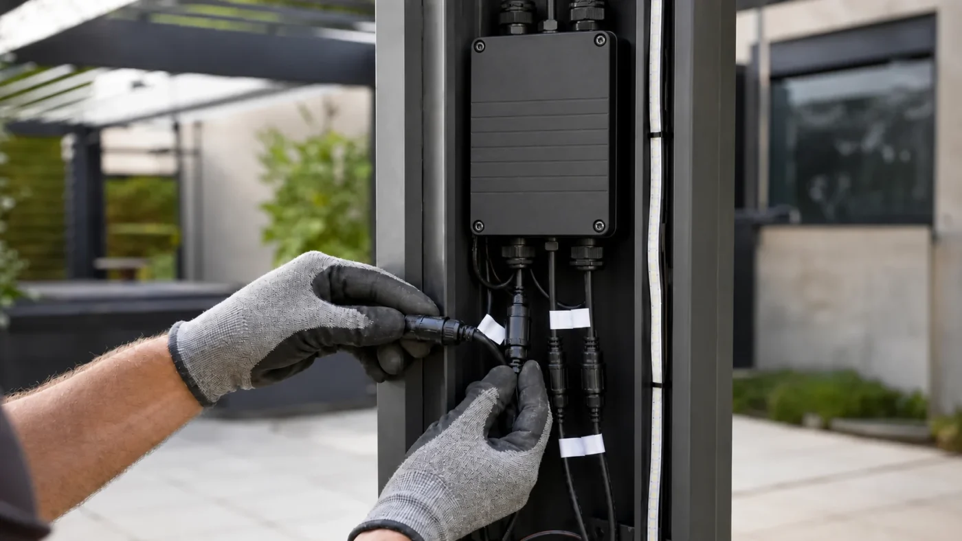
Design it out by validating the RF path inside the finished aluminum assembly. Open-air range testing is not enough for a louvered pergola with closed beams, powder-coated covers, motors, long cables and LED electronics.
Aluminum can reflect and attenuate radio energy. An antenna pressed against a metal wall, coiled inside a control box or routed beside a switching power supply may perform very differently from the same antenna on a factory bench. The user may experience this as an intermittent fault: the command works from one side of the patio, then fails behind a glass door or under a closed roof.
Silicon Labs’ antenna design guidance covers the fundamentals that matter here, including antenna efficiency, impedance, radiation pattern and the effect of the surrounding environment. The OEM implication is practical: receiver position and antenna routing belong in the mechanical drawing, not in an installer’s spare space.
Controls to include in the product design
- Define a receiver location with predictable clearance from large metal surfaces, motor bodies and high-current wiring.
- Show the approved antenna route in the assembly documentation. Do not leave it loose inside the beam.
- Test with the final profile, cover, gasket, fasteners, powder coating and wiring harness installed.
- Test from realistic operating positions: beside the house, behind glazing, at the dining table and at the edge of a multi-zone installation.
- Document regional radio versions and do not change the antenna, transmitter power or firmware after compliance planning without review.
VLEDSTAR’s guide to preventing RF signal problems in aluminum pergolas expands this into an OEM test sequence. A useful target is not an impressive catalog range; it is repeatable control at the positions where dealers and homeowners actually stand.
2. “The app is smart, but the system is not usable when Wi-Fi fails”
Design the app as an additional interface, not the only path to a working pergola. Local control should remain available for commissioning, everyday use and recovery.
Cloud accounts, routers, passwords, phone permissions and firmware updates are outside the pergola frame. They can still determine whether the product feels reliable. A homeowner who cannot open the roof because the router changed its password does not care which layer failed.
An OEM control hierarchy should make the local path obvious. A typical structure can include an RF remote for immediate control, a physical or touchscreen interface for commissioning and local use, and app control for scenes, remote access and integration. This is also easier for dealers to explain than a product that depends on a single onboarding flow.
When evaluating future interoperability, use standards information rather than marketing assumptions. The Connectivity Standards Alliance describes Madde around simplicity, interoperability, reliability and security. Whether an OEM uses Matter, a dedicated app or another ecosystem, the engineering rule remains: connected features should extend dependable local behavior.
Pairing should also be designed for service. Assign a clear reset procedure, a visible pairing state, a channel map and a way to test outputs without requiring a customer account. If the installer needs a phone, a cloud login and three unrelated apps just to confirm motor direction and lighting zones, the commissioning process is already too fragile.
3. “Why are there separate remotes for the roof, lights and screens?”
Reduce interface fragmentation by consolidating functions where the electrical architecture allows it. A single control map is easier to learn, test, package and support than a collection of independent receivers.
Multiple receivers multiply the failure points. Each may have a different pairing method, antenna location, power supply, channel convention and replacement process. The result is a premium pergola that behaves like several unrelated products attached to one frame.
For many residential and light commercial models, an integrated controller can coordinate mono or RGB lighting, linear actuators, tubular motors and weather inputs. VLEDSTAR’s entegre pergola kontrol sistemi is one example of this architecture, combining RF remote, app and touchscreen control with multiple motor, lighting and sensor outputs.
Integration does not mean forcing every accessory onto one board. Larger projects may need distributed modules. The important point is that the control map is intentional. For every output, define its channel, feedback behavior, maximum load, cable route, service method and user-facing name.
| Complaint | Architecture cause | Design-out measure |
|---|---|---|
| “I need three remotes.” | Independent receivers and inconsistent channel mapping. | Use one documented control hierarchy and group channels by user task. |
| “The lights work, but the roof does not.” | Separate power, pairing or protection behavior is not visible to the user. | Provide local diagnostics and a commissioning sequence that tests every output. |
| “The installer cannot identify the replacement.” | Generic modules are hidden without a service label or revision record. | Label the control box, harnesses, firmware version and regional BOM. |
4. “The louvers do not move together or stop at the same position”
Design synchronization around mechanical reality, not only motor specifications. The controller, actuator limits, linkage, frame squareness and commissioning procedure must be treated as one motion system.
Uneven movement is often blamed on the motor, but the root cause may be a frame that is out of square, a linkage under unequal load, inconsistent limit settings, cable voltage drop or an actuator that has lost its reference. A smart controller cannot compensate for uncontrolled mechanical variation.
OEMs should define how the system establishes and preserves position. Use electronic limits or an approved calibration method where appropriate, and include a controlled re-homing procedure after power interruption or service. If an actuator includes limit switches or position sensing, the manual should explain what the installer can adjust and what requires a replacement or engineering review.
Obstacle behavior deserves equal attention. A roof that continues driving against a blocked louver can damage both the mechanism and the customer’s confidence. Define current protection, stop behavior, retry logic and the fault indication. Then test with realistic friction, temperature and assembly tolerances instead of only a free-moving sample.
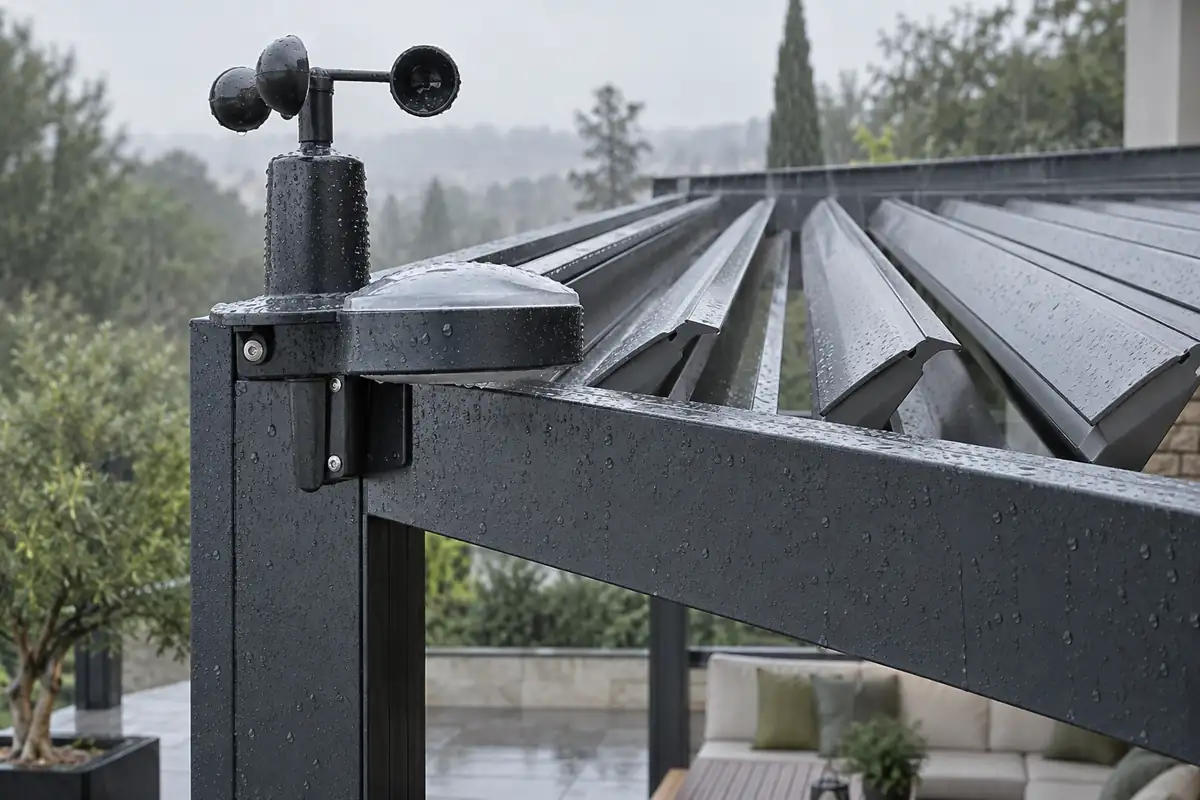
5. “The rain sensor closes late, or the wind automation is too sensitive”
Design synchronization around mechanical reality, not only motor specifications. The controller, actuator limits, linkage, frame squareness and commissioning procedure must be treated as one motion system.
Weather automation is valuable only when its priorities are unambiguous. Wind, rain, sun, snow, manual commands, app commands, and scheduled scenes can all compete for control. If the product does not define which command wins, installers and customers will discover the hierarchy through failure.
Write the behavior as a state model. For example, define what the controller does in normal operation, during a weather alarm, after a sensor signal disappears, during a power recovery, and when the system is placed into a winter or maintenance lockout. State whether lighting remains available when roof movement is blocked. State how a manual command is handled when the safety condition is active.
A bounded manual override is usually more useful than an unrestricted override. Users need a way to operate the product during commissioning and normal use, while the controller still protects against conditions it cannot prove to be safe. The design principles in this manual override and fail-safe control guide can be translated into a product-specific priority table.
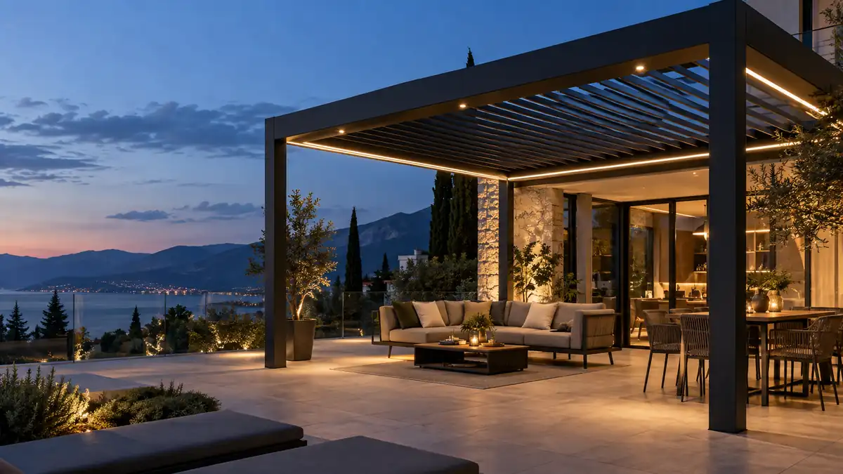
6. “The lights flicker, dim unevenly or do not match the product promise”
Design synchronization around mechanical reality, not only motor specifications. The controller, actuator limits, linkage, frame squareness and commissioning procedure must be treated as one motion system.
Integrated lighting raises the value of a pergola, but it also adds electrical variables inside a conductive outdoor structure. Long low-voltage runs can create voltage drop. A driver that is undersized or poorly matched to the dimming method can produce flicker or a limited dimming range. Mixed RGB, RGBW, CCT and mono zones can create an inconsistent user interface if the channels are not defined before assembly.
Use a load schedule for every product configuration. Record the LED technology, voltage, total wattage, driver margin, maximum run length, connector type, waterproofing method, channel assignment and expected scene behavior. Then test the lowest and highest brightness settings, power-up behavior, simultaneous motor movement and the longest approved cable route.
VLEDSTAR’ın pergola aydınlatma serisi includes recessed downlights, spotlights, LED strips, wall lights and accessories for integrated systems. The advantage of sourcing these elements as a coordinated package is not only purchasing simplicity; it gives the OEM one technical conversation about light output, control, connectors and structural integration.
7. “The system is impossible to service after installation”
Design serviceability as part of the product, not as an afterthought behind a sealed beam. Dealers need a safe way to identify, test and replace control components without damaging finished structure.
Outdoor products are exposed to weather, installation variation and years of use. Even reliable electronics need a recovery plan. A compact controller is valuable only if the installer can reach it, identify it and replace it with the correct revision. Waterproof connectors help, but only when they are keyed, labeled and protected from strain.
Include a service layer in the OEM design review:
- A defined access panel or removable section that does not compromise water management.
- Labels for input power, motor zones, lighting zones, sensors and spare connections.
- A QR-linked manual or printed service sheet with pairing, reset, limit and fault procedures.
- A replacement policy for controllers, remotes, power supplies and harnesses, including revision compatibility.
- A commissioning checklist that records channel assignments and final test results for the dealer.
For products sold in the European Economic Area, compliance documentation should also remain aligned with the shipped configuration. The European Commission explains that manufacturers are responsible for conformity assessment, the technical file, the EU Declaration of Conformity and CE marking where applicable; see the official CE marking guidance. A late change to an RF module, antenna, power supply or firmware can therefore create both a service issue and a documentation issue.
A practical pre-launch test plan for pergola OEMs
The best way to design out complaints is to test the assembled product under the same conditions in which it will be sold. Use a repeatable test matrix rather than a single showroom demonstration.
| Test area | Test the complete system for | Record before release |
|---|---|---|
| RF control | Range, dead spots, aluminum covers, glazing, motor noise and realistic user positions. | Approved receiver and antenna location, regional version and pass conditions. |
| Local and app control | Pairing, reset, power loss, router loss, account handover and local fallback. | Commissioning steps a dealer can complete without engineering support. |
| Motion | Synchronization, end limits, obstacle response, repeated cycles and recovery after interruption. | Calibration method, fault behavior and mechanical tolerance limits. |
| Hava durumu mantığı | Trigger delay, hysteresis, priority, manual override and sensor failure behavior. | Documented thresholds and the user-facing explanation for automatic actions. |
| Lighting | Full load, low dimming, longest cable, color scenes, simultaneous motor operation and restart. | Load schedule, driver pairing, channel map and approved wiring limits. |
| Hizmet | Access, labeling, connector replacement, module swap and post-service recommissioning. | Spare-part matrix, revision rules and service documentation. |
This is where an experienced control and lighting partner adds value. VLEDSTAR has worked in LED lighting since 2010 and now supports integrated pergola lighting and control solutions, including joint R&D, customized control packages and manufacturing for outdoor structure brands. The company’s factory and capability profile provides the relevant background, while its pergola aydınlatma çözümleri sayfası shows how lighting, controls and OEM support can be planned as a connected supply package.
How to turn complaints into product requirements
Do not copy a support ticket directly into a manual. Translate it into a measurable design requirement:
- Capture the real operating condition. Record the frame configuration, control position, cover state, weather, load, firmware and installation details.
- Separate the symptom from the layer. “Remote failed” may be RF attenuation, power loss, pairing, channel mapping or sensor priority.
- Assign ownership across the bill of materials. The frame team, motor supplier, lighting team and controls engineer must share one interface definition.
- Build the fix into the next validation sample. Test the complete product, not an isolated replacement component.
- Update dealer documents and spare parts together. A technical fix that cannot be installed consistently will return as a new complaint.
This process changes the business conversation. Instead of asking whether a controller has more features, the OEM asks whether the product is predictable, recoverable and serviceable across the entire dealer network.
Frequently asked questions
Why do smart pergola remotes work in testing but fail after installation?
The final aluminum structure can attenuate or detune the RF path, while motor cables, LED drivers, glazingand access covers can change the electrical environment. OEM validation should test the completeassembled pergola, not only an open-air controller and remote.
Should a pergola controller support local control without the app?
Yes. A local RF remote, wall control or physical commissioning method gives installers and users a recoverypath when Wi-Fi, cloud services or account access are unavailable. App control should extend the system rather than become its only usable interface.
What should an OEM test before launching a smart pergola?
Test RF range in the finished aluminum frame, motor synchronization, limit behavior, sensor thresholds,lighting loads, power interruption recovery, pairing, service access and regional compliance documentation.Repeat tests across the production configurations dealers will actually install.
Design the next pergola around fewer service calls
If your product line still uses separate remotes for louvers, lights and accessories, or if the controller location was chosen after the frame was finalized, the next improvement is probably architectural. VLEDSTAR can help review the control map, lighting loads, sensor logic, RF path and OEM packaging before those decisions become warranty costs.
Explore the integrated pergola control system veya VLEDSTAR ile iletişime geçin with your current motor, lighting and sensor requirements.

Talebinizi Bize Gönderin