


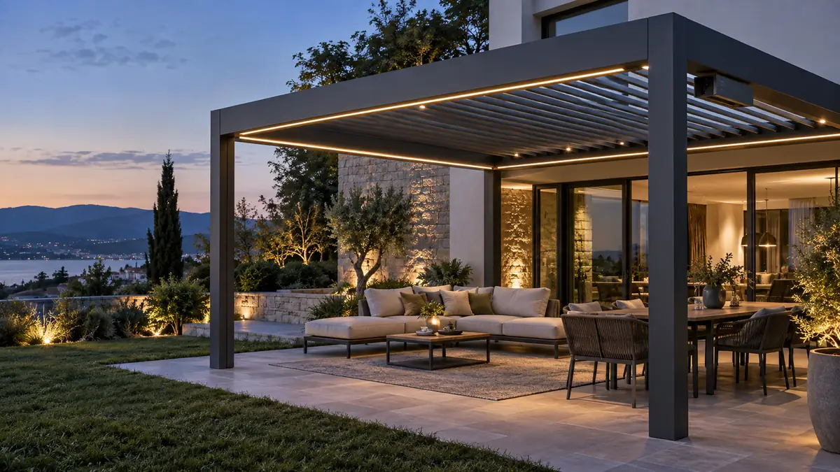
For a pergola manufacturer, the expensive part of a warranty claim is not always the replacement component. It is the complete service event: diagnosing the fault remotely, dispatching a technician, removing finished trim, replacing a part that may not have failed, restoring settings, and managing customer expectations. A control system designed only to demonstrate well in a showroom can create all of those costs in the field.
The better approach is to treat warranty prevention as a product-design discipline. The lighting, motors, sensors, power supply, connectors, firmware, installation method, and service procedure should be developed as one platform. This does not mean every pergola needs the same configuration. It means every configuration should have a known electrical architecture, a defined safety hierarchy, repeatable assembly steps, and a clear path to diagnosis.
Core position: the lowest-warranty pergola is not the one with the fewest features. It is the one whose features are integrated, tested, and serviceable as a system.
Why pergola warranty costs often start in the control architecture
Outdoor pergolas combine several systems that are individually familiar but operationally interdependent. A typical product may include louver actuators or tubular motors, LED downlights or strips, a power supply, RF or app control, and wind, rain, sun, or snow inputs. The roof may also be installed into different frame geometries by different dealer teams.
That combination creates failure paths that a component-by-component purchasing process can miss. A controller may be electrically compatible with a motor but poorly matched to its travel feedback. A light may meet its own ingress target but be installed with a connector that allows water into the harness. A sensor may work in isolation but send a command that conflicts with a manual action or a winter lockout.
These are system-integration problems. Customers experience them as “the pergola stopped working,” “the lights flicker,” or “the roof will not close.” The warranty department then inherits a problem that originated months earlier in specification, sourcing, assembly, or commissioning.
Public warranty policies in the outdoor-living market commonly separate structural coverage from electronics, motors, controls, wiring, and lighting. That separation reflects a practical truth: electronic and electromechanical subsystems need their own environmental, compatibility, and service strategy. Manufacturers should use that distinction during design, not only when writing warranty terms.
1. Start with a system failure map, not a component list
Before selecting a controller, map the complete operating chain for each product family. Document what supplies power, what issues commands, what confirms movement, what blocks unsafe movement, and what the installer can replace without changing the whole system.
A useful failure map asks five questions:
- What happens if mains power is interrupted during movement?
- What happens if a motor reaches resistance before its expected position?
- What happens if a weather sensor is disconnected or reports an invalid state?
- What happens if wireless communication is lost but the local control remains available?
- Which part can be replaced independently: controller, power supply, receiver, sensor, harness, or motor?
The answer should be visible in the design. A service technician should not need to infer the system’s logic from symptoms. Status indicators, labeled connectors, stored configuration, and a documented reset process can turn a multi-hour investigation into a controlled replacement.
This is also where a modular architecture pays for itself. If the lighting channels, motor outputs, and sensor inputs are defined clearly, the manufacturer can maintain a smaller set of serviceable modules across different pergola models. Standardization reduces training time, spare-parts complexity, and the risk that a technician installs a visually similar but electrically unsuitable replacement.
2. Match control outputs to the real motor and mechanical load
Motor compatibility should be validated in the finished pergola mechanism, not only on a workbench. The controller must work with the motor’s voltage, current behavior, direction logic, limit strategy, feedback method, and expected duty cycle. The mechanical system must also move freely throughout the full travel range.
For louvered roofs, friction and alignment can change the electrical signature of movement. A control system that operates acceptably with a lightly loaded demonstration frame may trip protection or lose position when the blades, linkage, seals, temperature, and installation tolerances are all present. Retractable roof systems introduce a different set of concerns, including tubular motor compatibility, end limits, fabric tension, and obstruction behavior.
Do not rely on a generic statement such as “compatible with pergola motors.” Define the approved motor families and the conditions under which they are approved. Record maximum outputs, connection polarity, feedback assumptions, pairing steps, and the behavior of a motor that does not respond. If more than one motor is operated together, specify whether synchronization is electrical, mechanical, or both.
A controller with obstacle response or current protection can help reduce damage, but only when its thresholds are tuned to the mechanism. Protection that is too sensitive creates nuisance service calls. Protection that is too permissive can allow repeated stress on louvers, gears, or mounting points. The right setting is a product-level decision, supported by endurance testing and installation tolerances.
VLEDSTAR’ın pergola control unit platform is structured around multiple motor and lighting outputs, weather inputs, grouping, and OEM configuration. For a manufacturer, the value is not the number of channels alone. The important question is whether the channel structure can be matched to the motor architecture and then reproduced in production.
3. Design the outdoor enclosure and harness as part of reliability
An IP rating is useful only when the complete installation preserves the protection level. The enclosure, cable glands, connectors, mounting direction, drainage path, service cover, and unused ports all influence real-world performance. The IEC 60529 standard provides the formal framework for ingress protection classifications, but a rated enclosure cannot compensate for poor cable routing or an open connector facing upward.
For pergola control systems, the design review should include:
- Where condensation can form and how it can drain.
- Whether connectors are protected from direct water paths and capillary ingress.
- Whether the box remains accessible after the roof, lighting, and trim are installed.
- How cables are restrained so vibration and movement do not load terminals.
- Whether the enclosure temperature remains acceptable under sun exposure and maximum load.
- How installers identify spare, active, and service connections.
Plug-and-play wiring can reduce assembly errors, but only if the harness is keyed, labeled, and protected from incorrect mating. Waterproof connectors should not be treated as a substitute for installation discipline. A connector that is technically sealed but difficult to close correctly can still become a recurring field issue.
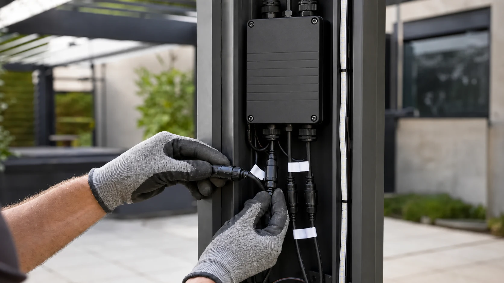
VLEDSTAR’s integrated approach combines control units with wiring and connector solutions so that the electrical design can be evaluated as a complete kit. The entegre pergola kontrol sistemi page shows the intended relationship between lighting, motors, weather sensors, control modes, and the compact control box. Manufacturers should use that kind of relationship as the starting point for their own installation drawings and service instructions.
4. Make fail-safe behavior explicit before adding automation
Weather automation is valuable only when its priorities are unambiguous. Wind, rain, sun, snow, manual commands, app commands, and scheduled scenes can all compete for control. If the product does not define which command wins, installers and customers will discover the hierarchy through failure.
Write the behavior as a state model. For example, define what the controller does in normal operation, during a weather alarm, after a sensor signal disappears, during a power recovery, and when the system is placed into a winter or maintenance lockout. State whether lighting remains available when roof movement is blocked. State how a manual command is handled when the safety condition is active.
A bounded manual override is usually more useful than an unrestricted override. Users need a way to operate the product during commissioning and normal use, while the controller still protects against conditions it cannot prove to be safe. The design principles in this manual override and fail-safe control guide can be translated into a product-specific priority table.
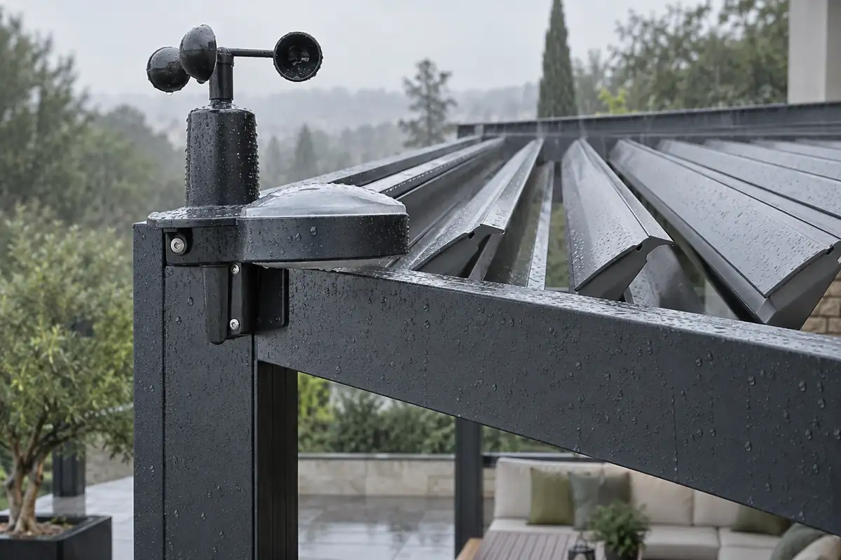
Fail-safe does not mean that every fault must shut down every function. A sensor fault may need to inhibit roof movement while leaving low-voltage lighting available. A communication fault may need to preserve local control. A temporary weather alarm may require a clear recovery rule rather than a permanent lock. Separating these functions reduces customer frustration without weakening the safety intent.
5. Reduce warranty labor through design-for-service
Warranty cost is strongly affected by how long it takes to identify and access the failed part. Design-for-service should be reviewed before the first production sample is approved.
Provide a short diagnostic path
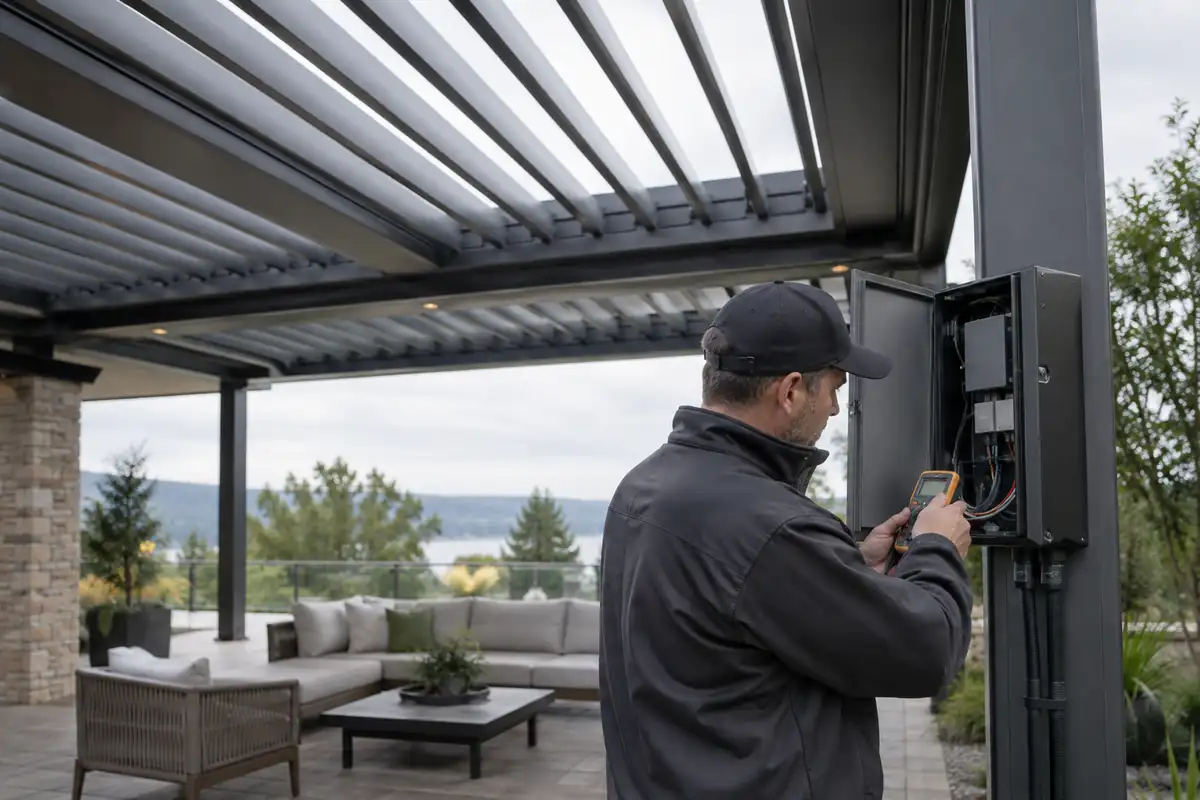
The installer should be able to confirm power input, controller status, output activity, motor response, sensor state, and pairing status in a logical sequence. A small number of meaningful indicators is better than a display full of codes that are not documented in the field manual.
Preserve configuration during replacement
If replacing a controller requires rebuilding every group, scene, travel limit, and sensor association, the service visit becomes longer and more error-prone. Where appropriate, provide a controlled backup, a commissioning file, or a repeatable programming procedure. Keep the procedure tied to the exact firmware and hardware revision.
Make access part of the frame design
A compact control box is useful only if the installer can reach it. Provide a defined access panel, enough space for connectors and bend radius, and a mounting method that prevents the box from moving inside the profile. If access is impossible after installation, even a simple relay or receiver fault can become a structural disassembly job.
Replace modules, not finished assemblies
When a failed part can be isolated to a controller, sensor, connector, power supply, or motor, the manufacturer can avoid replacing an entire lighting kit or roof assembly. Modular service also produces better failure data because the returned part can be analyzed without the noise of a full-system replacement.
6. Build warranty prevention into the validation plan
Validation should represent the product as it will be sold, installed, and used. Testing a controller without the production harness, enclosure, motor, lighting load, and sensor logic can create false confidence.
A practical validation plan for a pergola control platform should include:
- Repeated motor cycles across the full mechanical travel range.
- Maximum lighting load with the enclosure at elevated ambient temperature.
- Power interruption and recovery during lighting and roof movement.
- Wireless range and interference checks after installation inside aluminum structures.
- Sensor disconnect, false-state, and recovery behavior.
- Water and condensation review of the complete mounted assembly.
- Connector mating, unmating, and harness strain checks.
- Installer commissioning with the actual production instructions.
- Service replacement using the spare modules and tools available to dealers.
Reliability testing should also be connected to change control. A new motor supplier, connector, LED strip, firmware build, enclosure revision, or wiring length can change system behavior. Define which changes require a full re-test and which can use a documented regression test. This is one of the advantages of working with an experienced integrated manufacturer: the supplier can evaluate the effect of a change across electronics, lighting, firmware, wiring, and assembly rather than treating each part in isolation.
7. Use one product platform without forcing one configuration
Manufacturers often face a trade-off between customization and reliability. Too many unique systems increase engineering and spare-parts burden. A single rigid system may not fit the different motor, lighting, and control requirements of every market.
The practical middle ground is a configurable platform with controlled variants. Keep the core enclosure, safety logic, connector standards, commissioning workflow, and service model consistent. Vary only the approved elements that must change, such as channel assignment, firmware behavior, motor interface, logo, enclosure finish, or lighting output.
This approach allows an OEM to offer different pergola models while preserving a familiar service architecture. It also makes field feedback more valuable. If a connector, sensor bracket, or firmware behavior creates a recurring issue, the correction can be applied across the platform instead of being lost inside one custom project.
VLEDSTAR supports this type of OEM and ODM development through its pergola aydınlatma çözümüs, including integrated lighting, control, customization, and manufacturing support. The company’s R&D and manufacturing background covers LED products and integrated control systems, which is important when the warranty objective depends on the interaction between both.
A manufacturer’s warranty-reduction checklist
Before releasing a new motorized pergola system, confirm that the team can answer these questions without referring back to the original designer:
- Which motor families and lighting loads are officially approved?
- What is the command priority when weather protection and manual control conflict?
- What is the safe state after sensor loss, communication loss, or power recovery?
- Can the installer diagnose the system using the production manual?
- Can the controller, sensor, harness, and power supply be serviced independently?
- Can the control box be accessed after the pergola is fully assembled?
- Has the complete assembly been tested in its actual enclosure and frame?
- Are firmware, wiring, connector, and motor changes controlled by revision?
- Can the supplier provide test records, wiring guidance, and technical support during pilot production?
If several answers are uncertain, extending the written warranty will not solve the underlying problem. It will only increase the cost of discovering it later.
Conclusion: design the claim out of the product
Warranty cost reduction begins before the first pergola reaches a customer. It begins when the manufacturer defines the control architecture, matches motors to the real mechanism, protects the harness, establishes a safety hierarchy, designs access for service, and validates the complete production configuration.
The strongest control-system partner should therefore contribute more than a box of electronics. The partner should help define motor compatibility, lighting loads, sensor logic, connector strategy, firmware behavior, OEM variants, production testing, and field support. That is how a feature-rich pergola becomes a repeatable product rather than a collection of parts.
Share your motor type, lighting configuration, sensor requirements, frame constraints, and target market with the VLEDSTAR engineering team. We can review the architecture and recommend an OEM control solution designed for integration, production, and long-term service. Explore the control unit platform veya VLEDSTAR ile iletişime geçin.

Talebinizi Bize Gönderin