


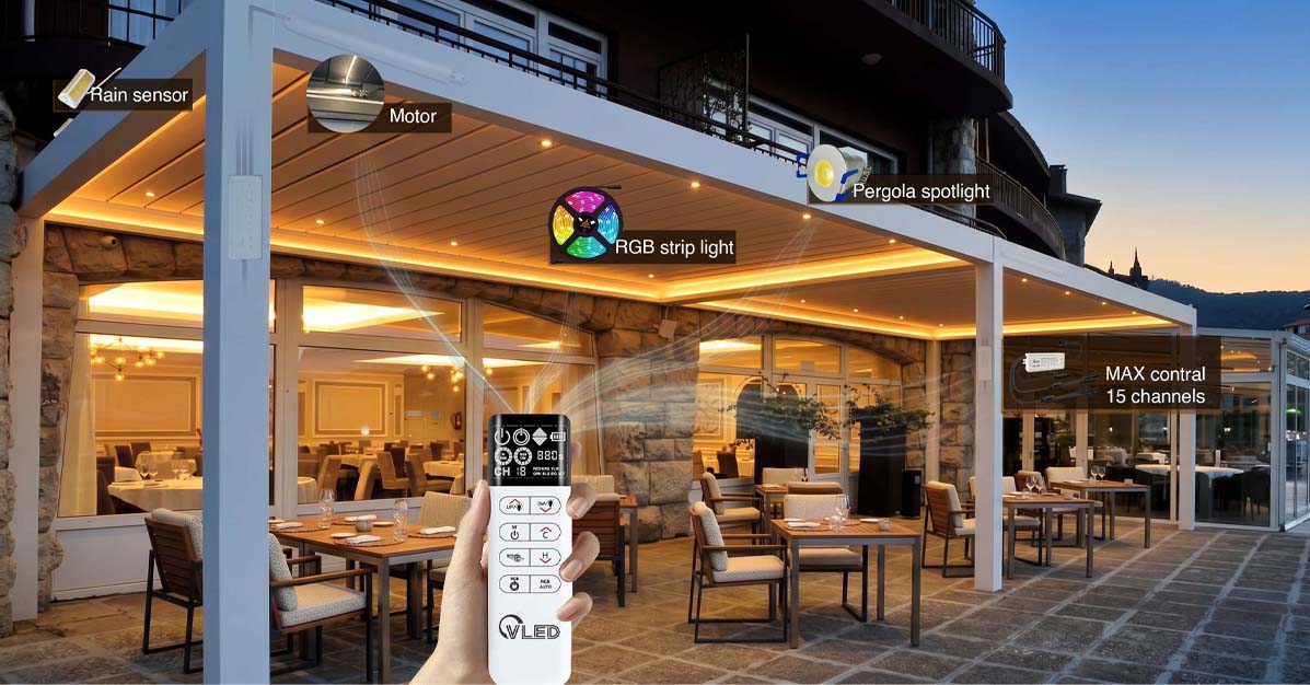
For pergola manufacturers, the remote is not a small accessory at the bottom of the packing list. It is the interface that tells installers whether the system feels engineered, tells dealers whether support will be repeatable, and tells homeowners whether the roof feels premium after the sale.
Key Takeaways
- Remote-controlled pergola louvers need a defined channel map before production, not after installation.
- Pairing should be treated as a support workflow with labels, logs, reset rules, and dealer documentation.
- RF design must respect market regulations such as Parte 15 de la FCC in the United States and the EU Radio Equipment Directive in Europe.
- The best OEM experience is not more channels. It is fewer mistakes during installation and faster diagnosis after handover.
Why Remote-Controlled Louvers Need OEM Thinking
Remote-controlled pergola louvers need OEM-level planning because a louver roof is a moving electrical product, not a static aluminum frame. A typical installation may combine roof motors, LED strips, screens, fans, heaters, rain sensors, wind sensors, and app control in one outdoor structure.
That combination creates a simple question for the end user: Which button does what? If the answer changes from one model to another, installers hesitate. If the pairing method is not written down, dealers improvise. If the remote label does not match the control box label, support calls become detective work.
We see this often in pergola control projects. The mechanical design may be strong. The aluminum profile may be clean. The drainage may work. Yet the user experience is judged by a remote that was specified late, documented lightly, and treated as an interchangeable component.
That is the wrong order. For manufacturers selling into Europe and North America, remote logic should be designed at the same time as motor selection, sensor strategy, lighting zones, enclosure location, and after-sales documentation.
Opinion: a premium pergola brand should not ask the installer to discover the control architecture on site. Channel layout, pairing behavior, and reset rules should be part of the product system before the first production batch leaves the factory.
Strengths and weaknesses of the current industry
The visible search results show strong demand for basic remote guidance, but most pages stop at compatibility, product operation, or homeowner-facing setup. JIECANG covers remote controller selection and protocol compatibility, StruXure highlights one-interface control, and several manuals explain channel operation after purchase.
This confirms the search intent: users want clarity on how remote-controlled pergola systems are organized, paired, and supported. However, the gap is also clear. The market has enough “how to use the remote” content. Manufacturers need a deeper guide on how to design the remote experience before it becomes a support problem.
For example, JIECANG correctly emphasizes that a universal frequency does not guarantee protocol compatibility. A remote and receiver must share the same communication logic, not just a nominal RF band. StruXure presents the customer benefit of controlling louvers, lights, fans, heaters, and screens from one interface. Installation manuals show how channels may be assigned to louvers, screens, and group modes.
Those are useful points, but they do not fully answer an OEM question: how should a manufacturer make channel layout predictable across models, batches, dealer territories, and replacement parts?
Innovation Space and Content Position
The strongest content position is to argue for a controlled system architecture. In this view, the remote is not a retail accessory. It is a low-cost, high-impact part of the manufacturer’s quality system.
This article therefore takes a professional opinion angle: channel layout should be standardized, pairing should be documented as a support workflow, and remote configuration should be designed to reduce field errors. The goal is not to add complexity. The goal is to make each pergola easier to install, explain, repair, and upgrade.
How Should Pergola Louver Channels Be Laid Out?
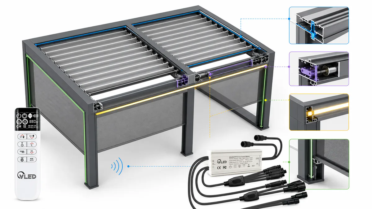
A pergola louver channel layout should start with the roof function, then group accessories around the way installers and homeowners think. In a manual indexed by Device.report, channels 1 and 8 are assigned to louver motors, channels 2 to 7 to zip screens, and group channels combine related devices.
That example shows the principle. Channels are not just numbers. They are a map of the pergola. A good map reduces wrong-button operation, incorrect pairing, and confusion when a second remote is added later.
Start With Function Priority
Louvers should usually occupy the first channel position because the roof is the defining movement of a louvered pergola. If a single roof motor exists, channel 1 should control it. If two roof motors operate separate bays, use channel 1 for bay A and channel 2 for bay B, unless the product family already uses a different established logic.
After the primary louver channels, assign screen motors by elevation or direction. For example, north screen, east screen, south screen, and west screen is easier to support than an arbitrary numbering pattern. Lighting can follow roof and screens, or sit on a dedicated lighting remote if dimming and color scenes need a different interface.
| Channel Range | Recommended Use | OEM Reasoning |
|---|---|---|
| Channel 1 | Main louver motor or first louver bay | Installers expect the primary roof movement to be the first control action. |
| Channels 2 to 4 | Additional louver bays, screens, or shade zones | These channels should follow the physical layout of the pergola. |
| Channels 5 to 8 | Screens, lighting zones, fan relay, heater relay, or spare expansion | Accessory channels should match the product configuration sheet. |
| Group channel | All louvers, all screens, or all movement devices | Group control is useful, but it must not override safety or sensor logic. |
| Scene channel | Preset positions or lighting scenes | Scenes are best used when the controller supports stable memory and clear feedback. |
Use the Same Logic Across Product Families
A channel map should not change because a distributor requested a small accessory variation. If a 3 m by 4 m pergola and a 4 m by 6 m pergola share the same control platform, keep the same naming and numbering logic wherever possible.
This matters when a dealer supports several models. A technician who learns one channel plan should be able to diagnose another model without starting from zero. Standardization also helps when replacement remotes ship years later.
Reserve Channels for Future Accessories
Manufacturers often under-specify channels because the base pergola only has one motor and one light. Later, the same customer adds screens, fans, or RGB lighting. At that point, a limited remote becomes a retrofit problem.
The better approach is to define base, plus, and premium channel maps. The base map can stay simple, while the control system still has a pathway for accessories. This gives sales teams room to upsell without forcing installers into improvised wiring and pairing work.
How Should Pairing Work in Production and On Site?
Pairing should be designed as a repeatable production and service process, not a hidden button sequence. Many manuals mention factory pairing, remote addition, direction change, deletion, reset, and app pairing. For OEMs, each of those steps needs a label, a test point, and a support script.
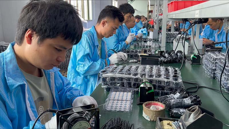
The best pairing workflow starts in the factory. Every receiver, motor, remote, and control box should leave production with a configuration record. This does not need to be complicated. A clear sticker, QR code, or printed test sheet can prevent hours of dealer confusion.
Factory Pairing Should Be Verified, Not Assumed
A factory-paired system still needs a final verification step. The operator should confirm open, stop, close, direction, limit response, sensor response, and accessory response before packing. For multi-bay roofs, each motor should be tested alone and in group mode.
The packaging should then protect that logic. A remote label that says “Ch 1 roof, Ch 2 east screen, Ch 3 west screen” is simple. It also prevents the installer from treating the remote as a blank device.
On-Site Pairing Should Be Short Enough to Survive the Field
Installers work around ladders, aluminum profiles, customers, weather, and schedule pressure. A pairing method that requires long timing windows, ambiguous LED flashes, or untranslated terms will fail in real installations.
A practical on-site pairing workflow should fit on one page. It should explain when to use add mode, when to use delete mode, and when a full reset is appropriate. It should also warn that reset can remove existing remotes or app records.
- Confirm supply voltage, receiver power, and motor connection.
- Select the target channel before entering pairing mode.
- Pair one device at a time and test movement immediately.
- Confirm direction before setting limits or presets.
- Record the final channel map on the installation handover sheet.
Direction Change Must Be Treated as a Controlled Step
For louver roofs, reverse direction is more than an inconvenience. It can affect rain close behavior, obstruction diagnosis, and customer confidence. Direction change should therefore sit in the installer guide, not only in a supplier manual.
The support document should use physical language. Say “press open and confirm the front edge of the louver rotates upward,” or match the movement to the drawing. Avoid vague terms such as forward and reverse when the installer may stand on a different side of the structure.
What Support Problems Should OEMs Design Out?
OEMs should design out the most common remote support failures: dead batteries, lost pairing, wrong channel selection, reversed motor direction, failed sensor priority, and app account confusion. A one-page troubleshooting table in a 2026 pergola manual already points users toward voltage, pairing, battery, and mainboard checks.
That list is familiar because remote support problems repeat across markets. The technical cause may differ, but the first customer complaint sounds similar: “the remote does not work.” A good support guide turns that sentence into a sequence of checks.
Separate Remote Failure From System Failure
The first support task is to decide whether the remote is the problem. A dealer should check battery condition, channel selection, distance, pairing status, receiver power, and local control buttons before replacing a motor.
This distinction protects warranty cost. If the receiver has power and responds to a wired button, the motor may be fine. If the remote operates one channel but not another, the issue may be channel selection or pairing memory. If nothing responds, power and control box checks come first.
Define Sensor Priority Before Complaints Happen
Weather automation can confuse users when the system refuses a manual command. Rain close, wind protection, snow lockout, and low-temperature logic should be explained in the user guide and dealer training.
The support question is not only “does the remote work?” It is also “is the controller intentionally blocking the command?” If the system closes louvers during rain, the remote should not appear broken. Feedback from the control box, app, or LED indicator helps reduce unnecessary service calls.
Respect RF Compliance and Market Variation
Remote systems must match the radio rules of the selling market. In the United States, RF devices are regulated under 47 CFR Part 15. In the European Union, wireless products fall under the Radio Equipment Directive.
This is not just a certification issue for the final paperwork. It affects product planning. A remote frequency, antenna design, enclosure material, receiver placement, and test setup may need adjustment by region. Manufacturers should confirm this early with their compliance partner.
Design for Outdoor Electrical Reality
Pergola control boxes live near water, heat, insects, UV exposure, and metal structures. Enclosure selection matters. The La IEC explica los índices de protección IP as a way to classify protection against dust and liquids, while NEMA enclosure type guidance is widely used in North America.
For OEMs, the key point is not to chase the highest printed rating without context. The enclosure, gasket, cable gland, drain path, connector, and mounting orientation must work together. A control box with good paper specifications can still fail if the cable entry points upward or the installer has no strain relief instruction.
What Should Be Written Into the OEM Control Specification?
An OEM control specification should describe the channel plan, device names, pairing steps, reset behavior, RF region, enclosure requirements, sensor priority, and service records. This document should guide product design, factory testing, installer training, and replacement-part support.
Many manufacturers already specify frame dimensions, aluminum grade, powder coating, fasteners, motor torque, and packaging. Remote-controlled louvers deserve the same discipline. The control system is where mechanical product quality becomes user experience.
Minimum Specification Items
A serious control specification should include the items below. The goal is to make each control package repeatable across production batches and dealer teams.
- Product configuration: number of louver motors, screen motors, lighting zones, fans, heaters, sensors, and app gateways.
- Channel map: exact channel number, device name, physical location, group channel, and reserved channels.
- Pairing method: factory pairing, add remote, delete remote, reset, direction change, limit setting, and app pairing.
- Labeling plan: remote label, control box label, motor label, cable label, and installation sheet.
- Electrical requirements: input voltage, low-voltage output, fuse or protection method, connector type, and grounding notes where applicable.
- Weather behavior: rain close, wind action, low-temperature lockout, manual override, and recovery logic.
- RF and market compliance: frequency band, regional variant, certification status, and allowed antenna configuration.
- Support process: troubleshooting order, replacement remote process, warranty evidence, and escalation rules.
Recommended Channel Layout for Manufacturers
There is no single channel map for every pergola, but there should be one logic for each product family. The following structure works well for many OEM systems because it starts with roof movement, then moves outward to accessories.
| Product Level | Typical Devices | Recommended Channel Logic |
|---|---|---|
| Standard roof | One louver motor, optional white LED | Channel 1 roof, channel 2 lighting, channel 3 reserved. |
| Dual-bay roof | Two louver motors, one light zone | Channel 1 bay A, channel 2 bay B, channel 3 all louvers, channel 4 lighting. |
| Screen package | Roof motor, two to four screens | Channel 1 roof, channels 2 to 5 screens by direction, channel 6 all screens. |
| Premium outdoor room | Louvers, screens, LED, fan, heater, rain and wind sensors, app gateway | Separate movement channels from comfort channels. Keep group movement away from lighting scenes. |
Support Documentation Should Match the Channel Map
The installer guide, homeowner guide, carton label, remote label, and dealer training sheet should use the same terms. If one document says “louver,” another says “roof,” and the remote sticker says “motor,” the support experience becomes weaker.
Consistency looks boring on paper, but it is powerful in the field. It lets a dealer ask, “What happens when you select channel 1 roof?” That single sentence is more useful than asking a homeowner to describe every button on the remote.
How Should Manufacturers Handle Replacement Remotes?
Replacement remotes should be handled through a controlled identification process. The support team needs the pergola model, control box version, receiver type, RF region, channel map, and pairing status before shipping a replacement remote.
This is where many brands lose margin. A homeowner loses a remote. A dealer orders a new one. The replacement arrives, but it cannot pair because the receiver protocol is different, the region code is wrong, or the original system used a proprietary rolling-code receiver.
A better process starts with product traceability. Each control box should carry a serial number or QR code linked to the control specification. The support team can then identify the correct remote, confirm whether dealer pairing is allowed, and send the right instruction sheet.
Do Not Treat Universal Remotes as a Warranty Strategy
Universal remotes can be useful for simple products, but they are risky for premium pergola systems. A remote may share a frequency and still fail if encryption, rolling code behavior, or receiver firmware does not match.
For pergola manufacturers, the warranty strategy should be compatibility control. Keep an approved remote list. Record discontinued receiver versions. Define what happens when an old remote line is replaced by a new one.
What About App Control and Smart Home Integration?
App control should extend the remote experience, not replace clear channel logic. StruXure’s operating system page shows the market direction: homeowners want louvers, lights, fans, heaters, and screens controlled from one interface. That convenience still depends on clean device naming and stable pairing.
When a pergola includes an app gateway, the manufacturer has two naming systems to manage: remote channels and app devices. Those names should match. If channel 1 is “roof,” the app should not call the same motor “awning motor 3.”
Smart home integration also changes support. A problem may come from the remote, gateway, Wi-Fi router, app account, cloud service, or third-party voice platform. The support guide should separate local RF control from app control. If local RF still works, the roof is not mechanically dead.
Keep a Local Control Path
Outdoor products need a fallback. A wall button, control box button, or paired RF remote gives the homeowner a local control path when Wi-Fi is unavailable. This also helps dealers diagnose whether a problem belongs to the motor system or the network layer.
For premium OEM systems, app control is valuable. But the remote remains the simplest support baseline. It should be robust, labeled, region-correct, and documented.
Practical Support Guide for Dealers and Installers
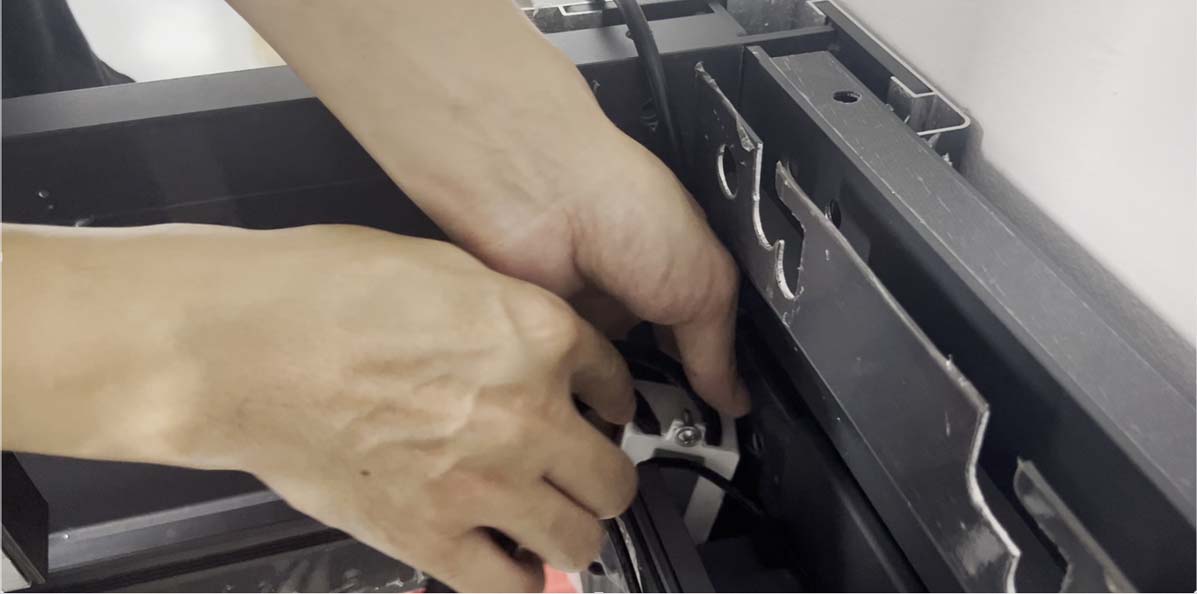
A dealer support guide should move from simple visible checks to deeper electrical checks. This prevents unnecessary part replacement and keeps field technicians from resetting a working system before they understand the failure.
The best structure is a sequence. Start with the remote and channel. Move to power and wiring. Then test receiver response, motor movement, sensor override, and app status. Only after that should the dealer replace hardware.
| Symptom | Likely Checks | Support Note |
|---|---|---|
| No movement from any channel | Battery, receiver power, control box input, fuse, local button | Do not replace the remote until receiver power is confirmed. |
| One channel works, another does not | Wrong channel, lost pairing, device not assigned, accessory power | Use the channel map before changing wiring. |
| Louver moves in the wrong direction | Direction setting, motor wiring, installation orientation | Correct direction before setting end limits or sensor actions. |
| Remote works but app does not | Gateway power, Wi-Fi band, account binding, app device record | Keep local RF control as the baseline test. |
| Manual command is ignored during rain or wind | Sensor priority, protection mode, recovery delay | Explain protection logic in the homeowner guide. |
Common Mistakes in Remote-Controlled Louver Design
The most expensive remote mistakes are usually small decisions made late. A manufacturer chooses a remote after the motor supplier is fixed, accepts a generic label, skips channel documentation, and leaves pairing instructions inside a supplier PDF.
That may work for a pilot order. It does not scale well across distributors, languages, and warranty years. The following mistakes are especially common.
- Using channel numbers without device names: users remember roof, screen, and light more easily than channel 1, 2, and 3.
- Mixing product families without a control matrix: small design changes can create hidden pairing differences.
- Letting group channels override logic too broadly: group movement must respect sensor and safety rules.
- Hiding reset instructions: reset is sometimes necessary, but it must be explained with consequences.
- Ignoring replacement years: support teams need a plan for remote models that will be discontinued.
- Leaving app pairing to the installer: app setup should have its own clear path, separate from RF pairing.
The OEM View: Remote Design Is Brand Design
Remote-controlled pergola louvers create a daily brand impression. Every time a homeowner opens the roof, adjusts shade, closes screens, or calls support, the control system either confirms the product’s quality or weakens it.
Manufacturers often invest heavily in the visible structure. That is necessary, but it is not enough. A louvered pergola is judged by movement, response, and confidence. The remote sits at the center of that experience.
Our position is simple: channel layout, pairing, and support should be treated as product design. The remote should be selected with the same care as the motor. The channel map should be reviewed with the same seriousness as the drainage path. The support guide should be written before the complaint arrives.
That approach helps manufacturers in three ways. First, it makes installations faster. Second, it reduces dealer support uncertainty. Third, it protects the brand when products stay in the field for many seasons.
Need a Cleaner Control Architecture for Your Pergola Line?
If you manufacture motorized pergolas for Europe or North America, define the channel map, pairing method, sensor logic, and replacement remote strategy before the next production run. A small control-system review can prevent a large after-sales problem.
PREGUNTAS FRECUENTES
How many channels does a remote-controlled pergola need?
A simple louvered roof may only need one or two channels, but an OEM product line should plan for expansion. Screens, lighting, fans, heaters, and group commands can quickly increase the channel count. The better question is how many functions must be clear to installers and homeowners.
Should louvers and lights be controlled from the same remote?
They can be controlled from the same remote if the interface is clear. Louvers need open, stop, close, and sometimes position control. Lights may need on, off, dimming, color temperature, or RGB scenes. If the remote cannot make those functions obvious, a separate lighting control path may be better.
Why does a remote pair with one pergola but not another?
The remote may use the same visible frequency but a different protocol, rolling-code method, receiver type, or region setting. This is why manufacturers should maintain an approved compatibility list and avoid treating all same-frequency remotes as interchangeable.
What should installers record after pairing?
Installers should record the final channel map, remote model, receiver or control box version, sensor behavior, app gateway status, and any direction or limit adjustments made on site. This record helps future support and replacement remote orders.
Can app control replace the physical remote?
App control is useful, but a physical or local control path remains important. Wi-Fi, accounts, gateways, and mobile apps add more support variables. A paired RF remote or local wall control gives the dealer a reliable baseline for diagnosis.

Pingback: Retractable Louvered Pergola Control Systems: Motor, Remote, and Sensor Requirements
Pingback: Retractable Pergola Controls: Motor, Remote & Sensors
Pingback: How Pergola Manufacturers Can Replace Separate Remotes with One Integrated Lighting and Louver Control System
Pingback: Actuator and Tubular Motor Control for Pergola Louvers: OEM Integration Guide
Pingback: How to Control Two Actuators, Two Mono LED Zones, and One RGB Zone from One Pergola Remote